NDT in Aerospace
Inspection
AEROSPACE
By Dr. Pascal Pinter
Ensuring Aerospace Component Quality with CT-Data Analysis and Visualization Software
The GE9X is the company’s most quiet, fuel-efficient, clean-burning and powerful commercial aircraft engine to date. Image courtesy of General Electric.
For as long as there has been commercial and military flight, aircraft component suppliers have been charged with providing dimensional and process control-related data.
Aerospace and defense manufacturing, and associated maintenance and repair operations (MRO), are undergoing some fundamental technology shifts right now. One of the drivers of this is additive manufacturing (AM), also known as 3D printing, which is having a profound effect on the way that air- and space-craft designers and part-replacement makers go about their work. Gone are the constraints of traditional manufacturing, replaced by a sense that the sky is quite literally the limit thanks to AM’s virtually endless design freedom and the development of printable, high-performance metal alloys. With this comes shorter supply chains, faster development and delivery cycles, and the ability to iterate at speeds never before possible.
Similar benefits are derived from the use of non-metal advanced materials for aerospace such as carbon fiber and glass- or ceramic-filled composites, some offering significantly higher strength-to-weight ratios than aluminum and even titanium. These materials provide a far greater degree of design freedom compared to their traditionally manufactured sheet metal counterparts, opening doors to greater flight efficiency.

Orientation analysis carried out on a glass-fiber-reinforced sheet-molding compound (SMC). Each direction is coded by a certain color. This orientation data can be used to obtain fiber orientation distributions over the thickness to validate flow simulations and to provide reliable data for the structural simulation. Image courtesy of IAM-WK / KIT (Institute for Applied Materials/ Karlsruhe Institute of Technology), Germany.
Validating integrity
Whether metal or composite, what’s needed first and foremost are ways to validate part integrity, whatever the manufacturing method. For as long as there has been commercial and military flight, those producing components for aircraft have been charged with providing dimensional and process control-related data to their OEM customers—but have left proof of raw material integrity to their suppliers in the form of material certifications.
However, particularly in the case of AM, with the associated transformation that happens during the solidification, sintering (L-PBF or SLM), photocuring, or deposition (EBM) processes, material certs alone are not always sufficient for flight-critical components. Similarly, when composites assume roles that their metal counterparts cannot, manufacturers using these materials must often peer deep inside their wares to fully evaluate their integrity. In all such cases, only computed tomography (CT) scanning will do.
Industrial CT scanning is similar to the technology used by medical practitioners to peer inside the human body, but employs a far more powerful X-ray source to do so. This capability allows manufacturers to see through practically any material with ease, digitally capturing 2D X-ray projection images, then reconstructing them into highly accurate 3D models via advanced software.
Aside from building 3D models such software can also analyze the wealth of information contained within them. This includes a range of dimensional and structural data that technicians can check for defects such as porosity, delamination, cracks, and other failure modes, all of which would otherwise go undetected. And because industrial CT’s scanning powers are limited only by that of the X-ray source and the amount of time spent “under the beam,” there is little that can’t be inspected.
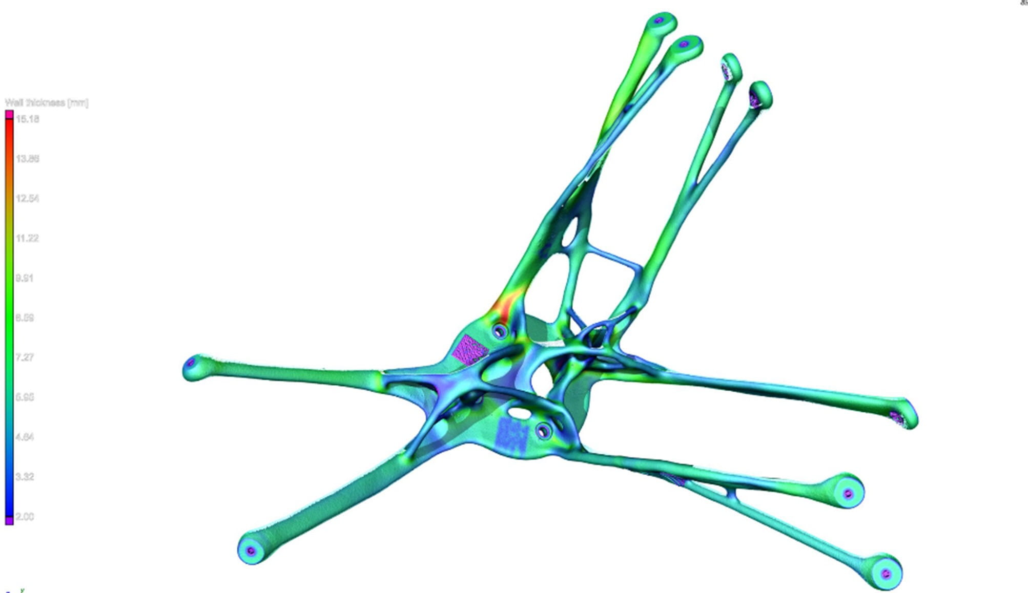
CT-data analysis and visualization software wall thickness analysis (WTA) on a topology-optimized, 3D-printed satellite bracket. The WTA shows the distribution of different wall thicknesses throughout the part. Image courtesy Volume Graphics
Powerful yet easy-to-use
Much of this capability is relatively new, driven by recent gains in high-performance computing and the development of powerful algorithms. Further, CT analysis and visualization software is much easier to use than it once was, allowing a layperson to do what once required a skilled technician. Because of this, complex engineering and metrology-related questions are answered far more easily than even a few years ago.
Consider an aircraft manufacturer striving to quickly validate the integrity of a new carbon-fiber component in R&D or in early manufacturing. CT scanning helps them analyze their interior structures for fiber orientation, layer thickness, delamination, and similarly hidden characteristics so that the manufacturer can be certain that the product will perform as expected.
Comparable arguments can be made for 3D-printed metal turbine blades and housings, fuel injectors, mounting brackets, landing gear, and the countless other parts now being made with laser-based powder bed printers and other AM technologies, all of which are routinely scanned with CT. Here, individual grains of metal powder are fused together via a laser or electron beam, making it imperative that manufacturers have the means to validate final metallurgical integrity.
Whether 3D printed or cast using traditional methods, one primary concern with any metal is porosity, which is hard to detect depending on the surrounding geometry without destructive testing. Not only does cutting up a finished part destroy the workpiece, what’s learned is far from comprehensive, since any adjacent, untested part sections might present completely different results. Here again, nondestructive CT scanning and analysis of a part and its surroundings together can not only identify porosity, but also inclusions, cracks, stratification, and even density, providing clues as to material strength and potential failure zones.
Local orientation histograms of a woven fabric are shown in yellow. Using the principal orientations of these histograms allows engineers to measure the local shear angle of the material after the draping process. Image courtesy of Volume Graphics.
Filling in the gaps
In many instances, CT analysis software can outstrip the capabilities of the CT scanner itself. For instance, when details within a very thick part or part feature are at the contrast limit of the material being scanned, intelligent image processing can use the available data to visualize details that are below the resolution limit. Other defect-analysis functions can deliver information as to why a component is good or bad—by evaluating the size and shape of internal artifacts relative to their distance from a wall, for example, and determining whether such defects might impact the component’s strength.
CT scanning and analysis play an increasingly important role in metrology as well. Because the digitally constructed 3D models are so accurate, users can extract all manner of dimensional data from a single platform. This is particularly important in the case of 3D-printed parts, given metal AM’s ability to create complex passageways and internal features that cannot be reached with coordinate measuring machines (CMMs) and traditional measuring tools. Further, both 3D printed parts, and many composite parts, can consist of free-flowing, organic shapes filled with curves and non-linear surfaces that are difficult to measure via conventional means. Given the right software tools and a high-quality CT scan, however, these metrological obstacles are easy to overcome.
As with traditional manufacturing, CT scanning is also used to help develop processes and then qualify first articles, a step known as the production part approval process, or PPAP. With some flight-critical components, manufacturers using novel materials or technologies might be required to perform 100% inspection after PPAP completion, but in most cases, 3D-printed and composite components can play by the same first-article inspection rulebook as those made using conventional means. In all cases, CT scanning can provide critical information.
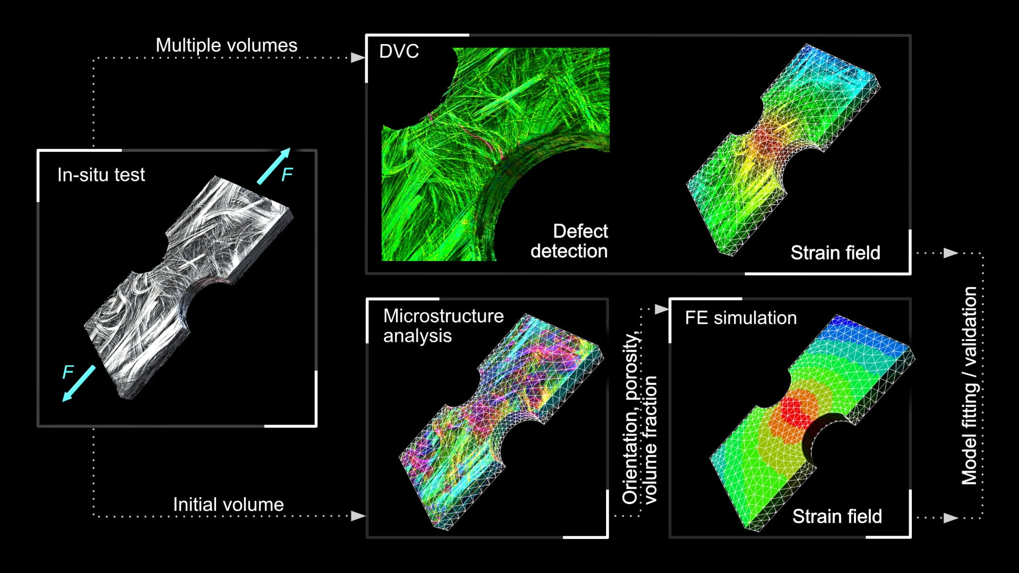
Mechanical in-situ testing is combined with digital volume correlation (DVC), using CT-data analysis and visualization software, to see if a part model is correct or if it should be adjusted (upper route). The analytical process can also be used as a crack-detection tool to see where damage occurs. Mechanical and material engineers can do an entire microstructure characterization on the first volume of an unloaded sample and then feed that data into finite element analysis (FEA) (bottom route), either to predict specific part behavior or to create a full comparative analytical model for product validation. Image courtesy of Volume Graphics
Countering CT costs
Although CT scanning equipment has come down in price with increased usage, it remains expensive relative to other metrology methods. But particularly in mission-critical aerospace applications, such considerations are strongly offset by the tremendous benefits afforded to CT users. The ability to peer deep inside any workpiece and visualize internal structures not only assures that products meet OEM specifications, but helps companies optimize their designs and manufacturing processes alike.
New materials and processes will continue to be developed for manufacturing applications in many industries. Some will be considered by the aerospace community, where the most delicate balance of weight, strength, aerodynamics, and cost is required for maximum performance. With such opportunity comes a need for extreme product safety, and the certainty that any part—whatever its design and however it was manufactured—will not fail in flight. Above all of its many attributes, this benefit is perhaps the greatest that CT scanning and analysis software can bring to the aircraft manufacturing shop floor and, increasingly, the production line.
Images Source: Volume Graphics, General Electric
Ian R. Lazarus is president and CEO of Creato Performance Solutions, providing leadership development, training, and solutions to support operational excellence.
Jim L. Smith has more than 45 years of industry experience in operations, engineering, research & development and quality management.

July 2021 | Volume 60 | Number 7