H2 Deck By Bold Name
h2 xxxxxx
H1 xxxxxx
h2 xxxxx

Ensuring the custom gage will work and meet the customer’s inspection needs is everyone’s top priority. By Mike Oddy
Standard Gages Will Not Work, Now What?
Test & INspection
H2 Deck Info By Paragraph Style Bold
Headline
Most machinists and inspectors have had this scenario occur at one time or another. You receive a drawing to manufacture or inspect a part. You have all the tooling and machining capabilities to make the part. You make some samples, then realize your current measuring tools are not capable of inspecting the part. In some cases, these samples may be generated using less than the preferred measurement methods or tools. Maybe you used the cutting tool or the mating part as the gage for the samples. This works until your customer gives you the order for thousands or hundreds of thousands of parts. Now there is a scramble to get qualified inspection tools and create an inspection plan to ensure dimensional accuracy per the part drawing or your customer’s specific requirements. In some cases, you are going to need to purchase or create new custom gages.
What is a custom gage? Is it a standard fixed limit gage manufactured on a gage blank per ASME B47.1 or is it a simple alteration of an existing fixed limit gage design? Does the product design require a completely new design gage, some type of fixture or variable type gage? This article will focus on alteration to existing plug gage designs as well as some complete special gage designs.
Some of the most common custom plug gage alterations are chamfers, radii, leads, and pilots applied to the ends of a plug gage. (See Fig. 1.)
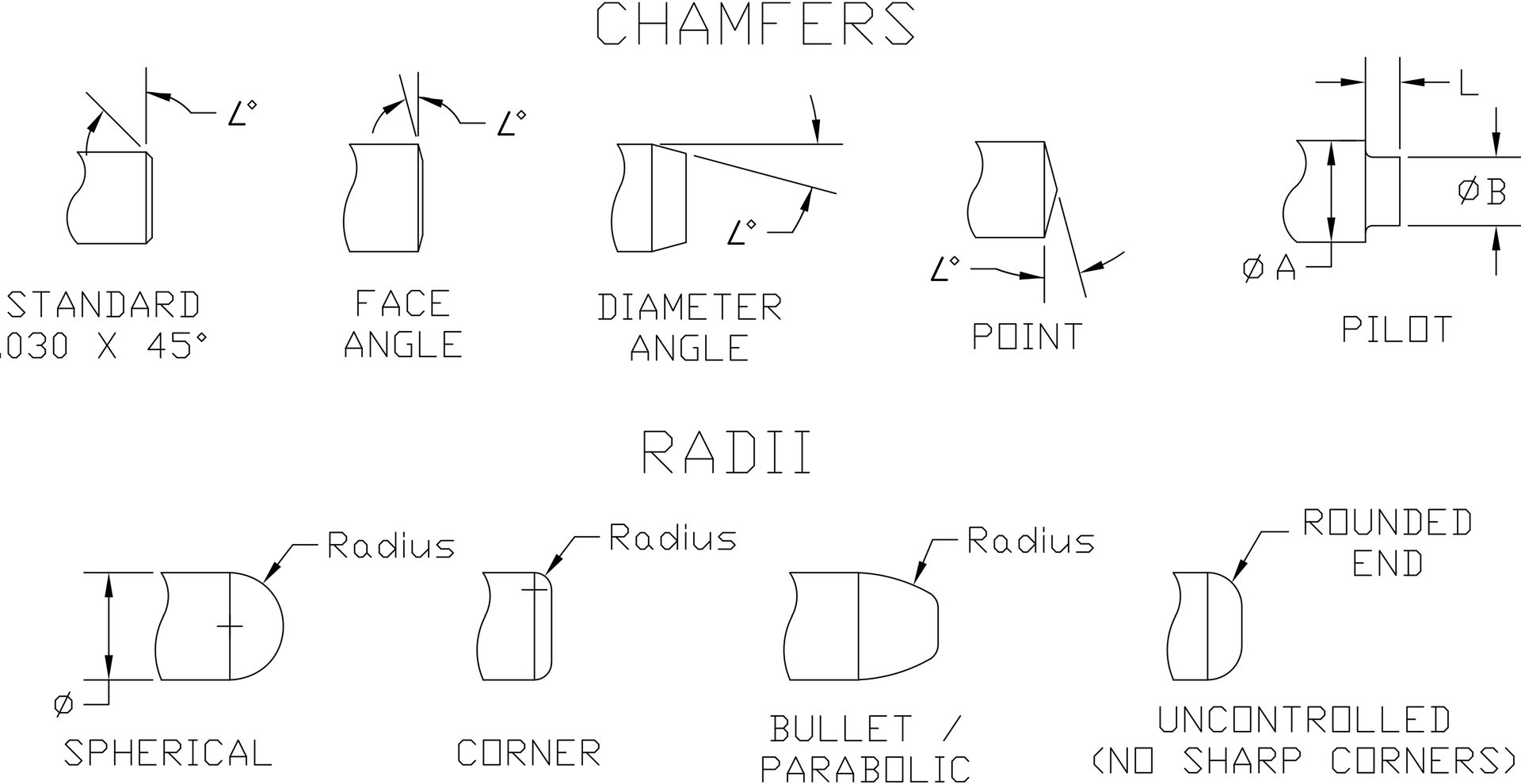
Figure 1.
In many cases, radii and chamfers are used to provide ease of entry or alignment to prevent damage to the part or assist in aligning the gage with the hole being inspected. In others, chamfers are used to create a clearance to a radius or some other feature in the bottom of the hole being inspected. (See Fig. 2 & Fig. 3 from a previous article)
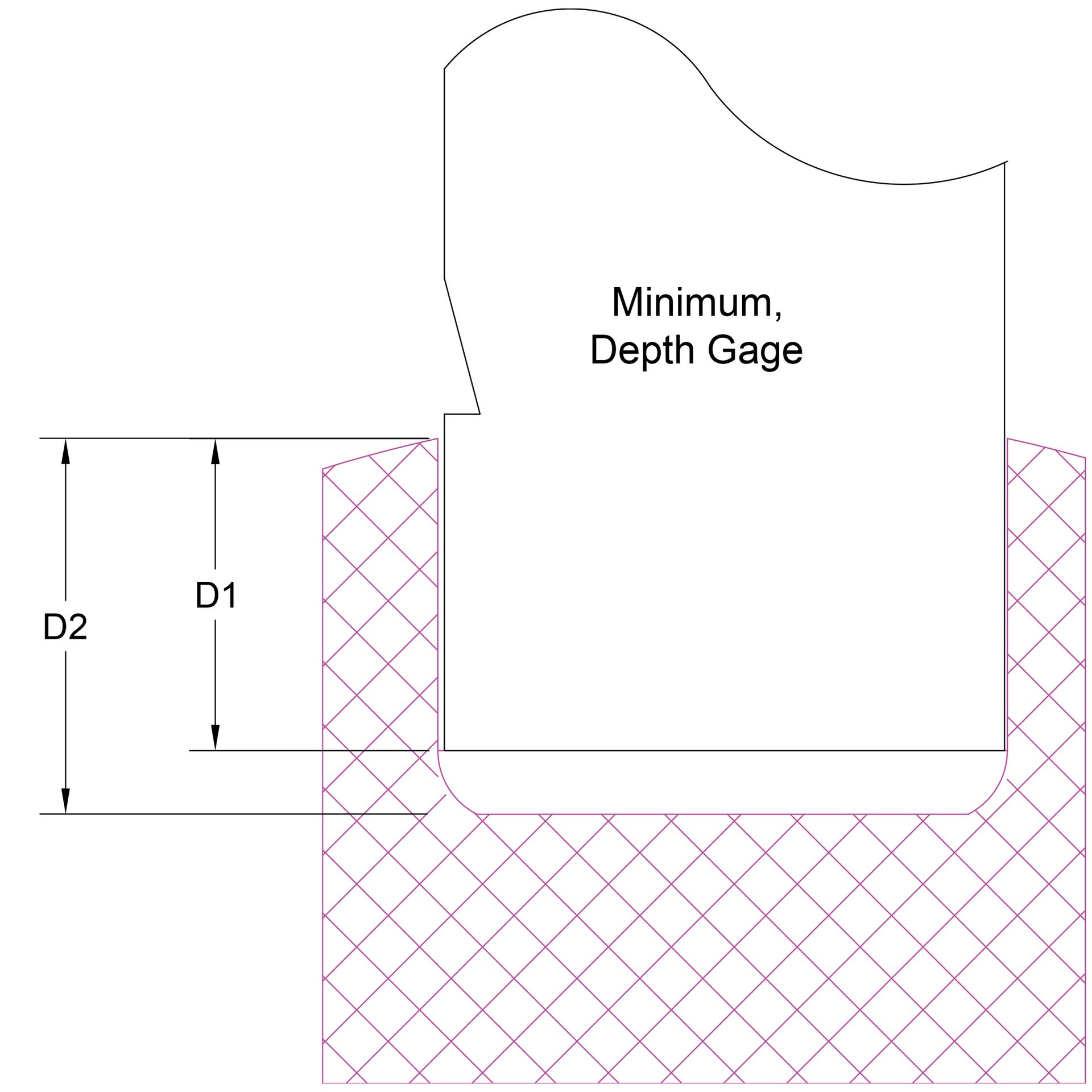
Figure 2.
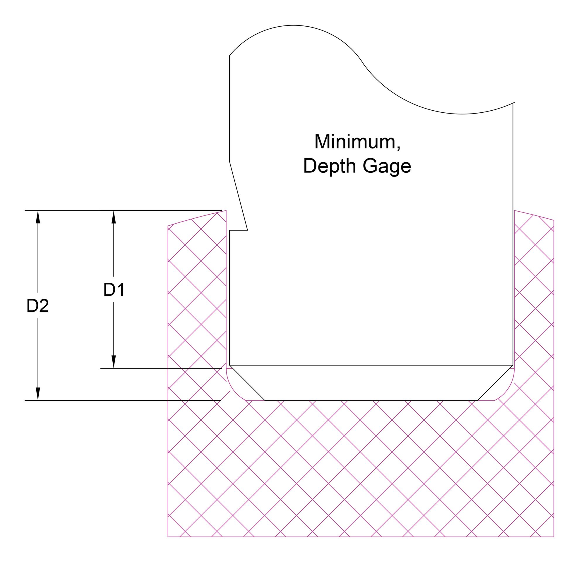
Figure 3.
Using chamfers on the plug gage to clear radii in the product hole allows the plug gage (typically the Go only, the No-Go plug gage is not supposed to fit) to reach the bottom of a blind hole. This allows for custom depth notch applied to the Go diameter plug gage to accurately confirm the hole minimum depth including the radius in the hole. In Fig. 2, the operator would assume that the hole needs to be made deeper to pass the (D2) minimum depth. The radius in the bottom of the product hole prevents the plug gage from reaching the required D2 depth. With the chamfer added to the Go plug gage, Fig. 3, the chamfer on the gage will ensure the minimum hole depth has been achieved by allowing the Go plug gage to reach the bottom of the hole (D2).
Custom plug gages with flats are a common gage alteration. The flats are added to allow air or fluid release in blind holes (Fig. 4, Air Flat). Flatted plug gages are used to clear or inspect a hole with a flat on one side (Fig. 5, D-gages) or two opposing sides (Fig. 6, DD-gages).
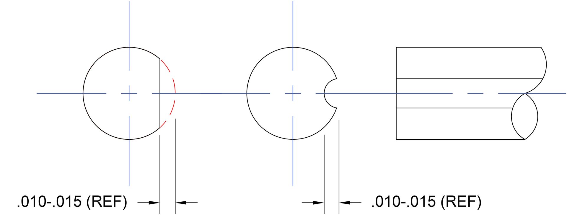
Figure 4.
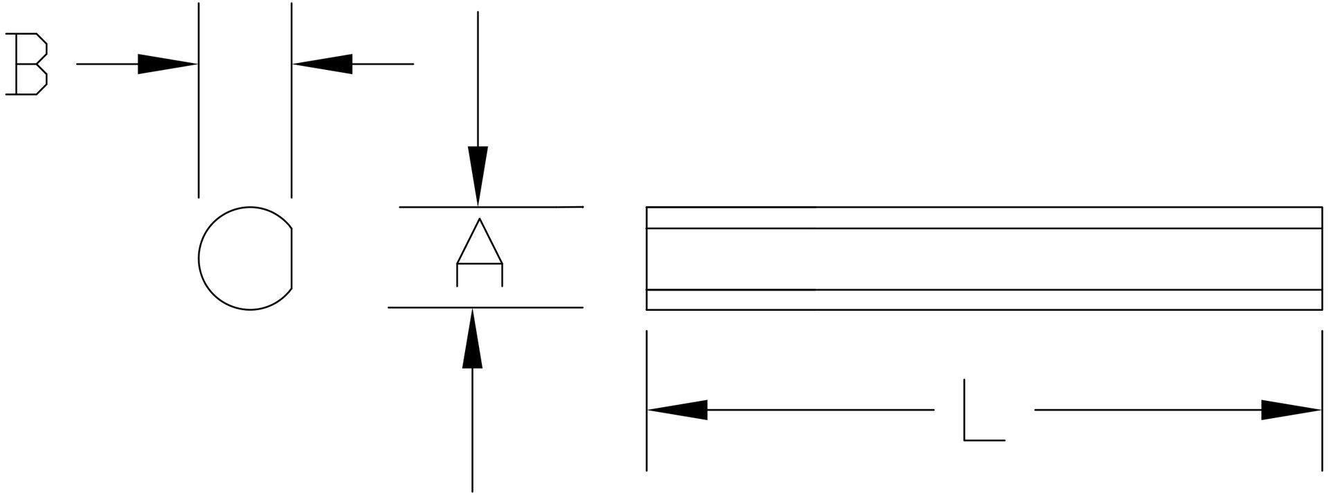
Figure 5.
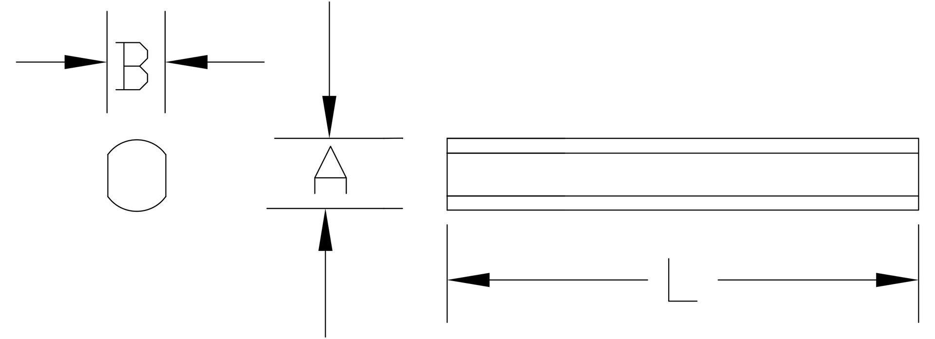
Figure 6.
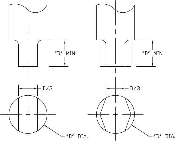
Figure 7.
The use of flatted blade or diamond gages are commonly applied to No-Go plug gages to inspect holes for oversized eccentric holes. (Fig. 7)
Per ASME B89.1.5-1998, Appendix C: “Flatted or diamond shaped NOGO plug gages are commonly used to detect ovality of holes. It is suggested that the remaining gaging surface be one-third of the gaging diameter.” (See Fig. 7, “D” = Diameter). “If the geometry is critical, we recommend that the holes be checked using single-element gaging. Flatted or diamond shaped members will not detect odd-numbered lobed conditions.”
Some custom plug gages are created completely from scratch to meet a specific product drawing specification. These gages may be developed to confirm co-axiality of multiple diameters in a hole, chamfers, or simply represent the mating part. This type of custom gage is completely dependent on the part drawing tolerances and designs. It is critical that the gage designer / developer has a full in depth understanding of what the gage can measure and more importantly what it does not measure. Remember, fixed limit gages are pass / fail inspection tools. Designing or using a fixed limit gage to inspect too many attributes at one time is a mistake and a big problem for the user. If you create a custom gage that measures multiple features at one time and the gage fails the part, what feature failed? What does the part manufacturer need to correct to get the part to pass the gage? Fixed limit gages, customs, or standards do not provide any actual measured values. If actual sizes or statistical process control (SPC) is required, one or more variable gages may be required.
The custom gages in Img.1 (below) show some examples of custom plug gages with multiple features. Usually, you will have one set of features that are controlled and used to inspect a single attribute of the hole. The other lengths, angles, and diameters are clearance features on the gage. i.e., the gage on the left is designed to check the min / max hole depth to the tip of the point on the front of the gage. To do so, the gage must clear the two diameters, the point angle, and the small diameter length.
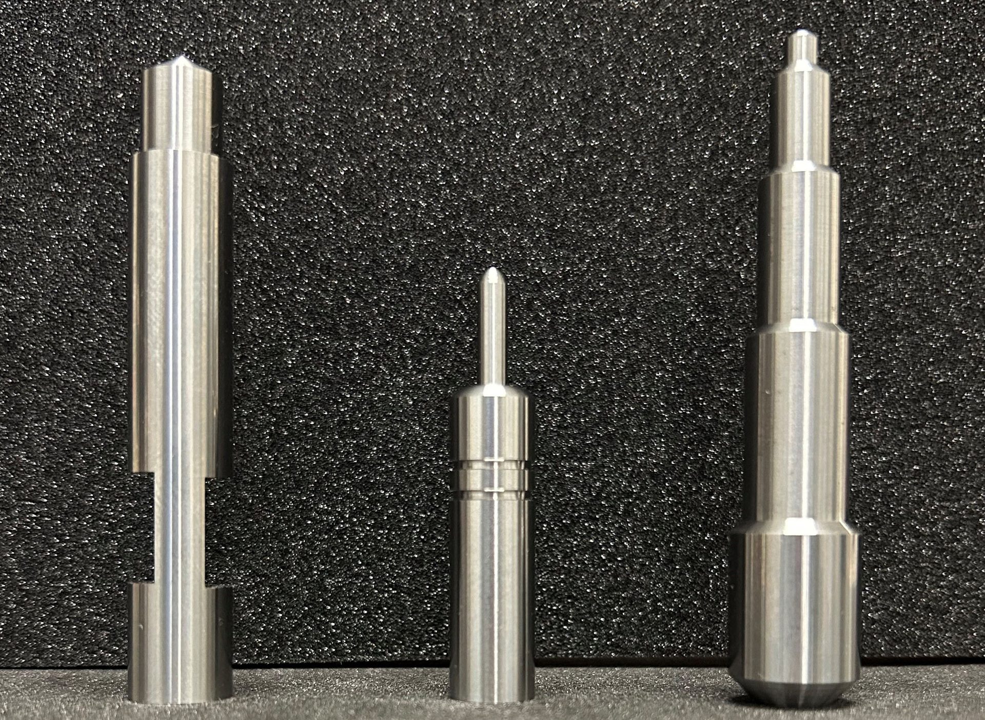
Image 1.
Probably the most important concept to understand when developing and ordering gages is, the product dictates the gage design, tolerance, and function. Gages do not dictate product tolerances or designs. If you already have a custom gage designed and gage drawing created, supply it to your gage distributor or gage manufacturer at the beginning of the custom gage quoting process. Even a rough sketch of the gage design you would like and a copy of the part drawing showing the part feature and tolerances to be inspected is a good place to start. Don’t worry about your drafting skills, many fixed limit gage manufacturers will start with the rough sketch and the part drawing and will work with you to offer suggestions or ask questions based on both. These suggestions and questions are to ensure the custom gage you order will inspect and pass parts to meet your requirements.
Critical custom gage considerations:
Cost
- Custom gages are developed based on standard gage blanks or completely special customer specific requirements.
- This makes custom gages more expensive to produce.
Non-returnable
- The custom gages are based on the customer’s part design.
- The gage manufacturer is unable to reuse or resell your custom designed gage.
- Be sure to work with your gage manufacturer to be clear and confirm what the gage does and does not measure.
- Signed off drawings are the best way to ensure both the custom gage user and manufacturer are aligned.
- Delivery
Long lead time.
- Custom gages are typically not stock gages and are made from scratch.
- Quote your custom gages at the same time you are initially quoting your customer's parts.
- This ensures you allocate the time and costs required for the gage manufacturer to make your custom gage.
Product design
- All gages are developed based on the products and features they designed to inspect.
When quoting or ordering custom gages communication is critical. Ensuring the custom gage will work and meet the customer’s inspection needs is everyone’s top priority. The user does not want to buy a gage they cannot use. The gage manufacturer does not want to make a gage the user cannot use. Clearly communicating by discussing and sharing the part drawing or portion of the part drawing showing the product specific feature and tolerances the gage is required to inspect is the best way to start. It is critical for all gages but, more so for custom-made gages, to properly store and protect your custom gages. They may be expensive and require a significant amount of time to replace them. If you take care of your gages, the gages will take care of you and your customer’s products.