H2 Deck By Bold Name
h2 xxxxxx
H1 xxxxxx
h2 xxxxx

Test & INspection
The search for perfection and accuracy continues at all levels and methods in the world of metrology. By Linda Goodwin-Marino
Uncertainty vs. Reality:
Standards in Optical Inspection
Test & INspection
H2 Deck Info By Paragraph Style Bold
Headline
“As far as the laws of mathematics refer to reality, they are not certain; and as far as they are certain, they do not refer to reality.”
- Albert Einstein, Address to Prussian Academy of Sciences (1921)
Fast forward 2025 and we are still striving for answers to uncertainty utilizing standards. Technologies apply contact and non-contact artifacts for measurement in dimensional inspection of everything manufactured. The following are some of the most innovative products and methods for verification of uncertainty in today’s manufacturing environment.
Opto-tactile Stepped Standards
Due to technical progress, the step standard has become one of the standard standards in optical and optical-tactile metrology. The field of application of the Optical Tactile Step Standards is in the calibration and verification of triangulation laser scanners, laser focus measurement systems and fringe projection systems.

Opto-Tactile Stepped Standards
See Figure 1 (right) Calibration standards based on gage blocks with diffuse reflecting or shiny measuring surfaces. Made entirely of carbide and therefore corrosion resistant. Customer-specific designs are available within wide limits.
Field of application: Optical length and coordinate measuring systems such as
- Triangulation laser scanners
- Laser focus measuring systems
- Fringe projection systems
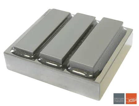
Figure 1: Stepped Standards for opto-tactile applications, photo courtesy of Kolb & Baumann
3D Calibration Standards
See Figure 2 (right) Test specimen according to VDI/VDE 2634 made of optically cooperative ceramic materials. The specially selected materials allow optical and tactile measurements and thus the direct linking of the two measuring principles.
Field of application: optical 3D CMMs such as
- Fringe projection systems
- 3D CMMs with optical touch probes
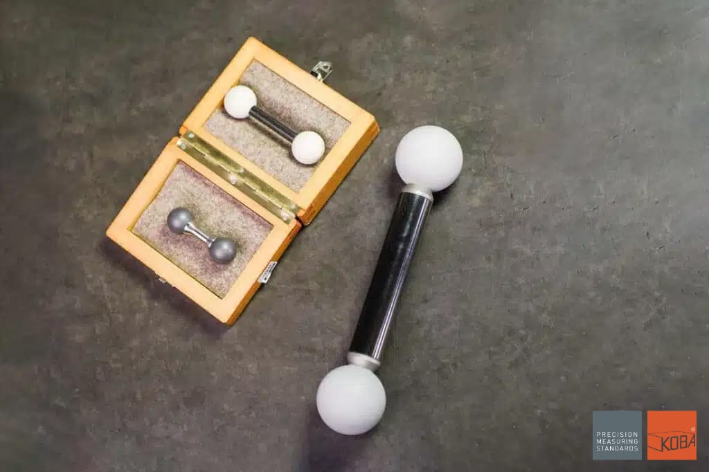
Figure 2: 3D calibration standards, i.e., dumbbells. Photo courtesy of Kolb & Baumann.
3D Calibration Standards
See Figure 2 (above) Test specimen according to VDI/VDE 2634 made of optically cooperative ceramic materials. The specially selected materials allow optical and tactile measurements and thus the direct linking of the two measuring principles.
Field of application: optical 3D CMMs such as
- Fringe projection systems
- 3D CMM’s with optical touch probes
Figure 2: 3D calibration standards, i.e., dumbbells. Photo courtesy of Kolb & Baumann.
Sphere Standards
See Figure 3 (right) Measuring spheres with diffuse reflecting surface in various designs. The spheres are made of carbide with a scratch- and corrosion-resistant surface that also allows tactile probing.
Field of application: Optical form and CMMs such as
- Triangulation laser scanners
- Video measuring systems
- Fringe projection systems
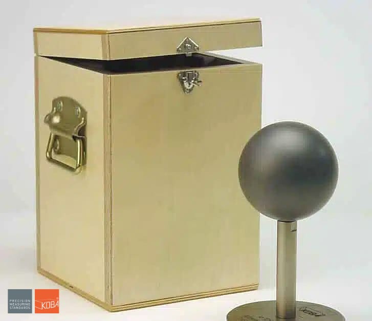
Figure 3: Sphere Standard. Photo Courtesy of Kolb & Baumann.
Koba Sphere-Beam
The KOBA sphere beam is a non-demountable sphere beam for monitoring and calibration of medium-sized CMMs. Ceramic spheres as probing elements, which are fixed in a stable position in a specially designed support, represent the long-term stable measuring lengths. Nominal lengths from 1,500 mm to 2,500 mm, with customer-specific pitches and ball diameters are available. Positioning of the KOBA sphere beam in a broad range within the volume of the CMM can either be made by using two light tripods in CFC or by a torsion-proof base on which a swivel arm is mounted.
Design Features:
The base consists of an integrated profile made of the highest quality ultra-high-modulus carbon fiber. This CFC profile is extremely rigid and dimensionally stable due to its design and the manufacturing technology used. To prevent dimensional changes caused by humidity, the load-bearing body is additionally equipped with a water-vapor-proof coating.
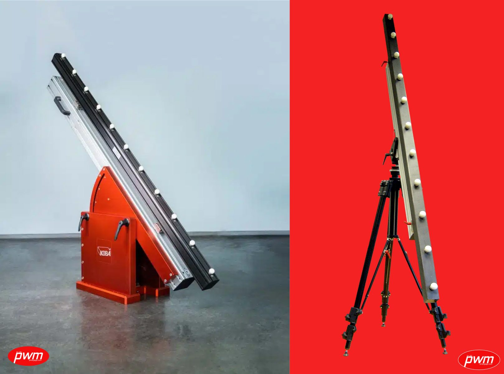
Figure 4: Sphere Beam, shown with base (left) and tripod stand (right). Photo courtesy of Kolb & Baumann
Koba Sphere-Beam
The KOBA sphere beam is a non-demountable sphere beam for monitoring and calibration of medium-sized CMMs. Ceramic spheres as probing elements, which are fixed in a stable position in a specially designed support, represent the long-term stable measuring lengths. Nominal lengths from 1,500 mm to 2,500 mm, with customer-specific pitches and ball diameters are available. Positioning of the KOBA sphere beam in a broad range within the volume of the CMM can either be made by using two light tripods in CFC or by a torsion-proof base on which a swivel arm is mounted.
Figure 4: Sphere Beam, shown with base (left) and tripod stand (right). Photo courtesy of Kolb & Baumann
Design Features:
The base consists of an integrated profile made of the highest quality ultra-high-modulus carbon fiber. This CFC profile is extremely rigid and dimensionally stable due to its design and the manufacturing technology used. To prevent dimensional changes caused by humidity, the load-bearing body is additionally equipped with a water-vapor-proof coating.
Artifacts for testing laser trackers.
Kolb & Baumann GmbH & Co. KG, leaders in the development of calibration standards, developed a large capacity artifact for verification of laser trackers (see figure 5, right).
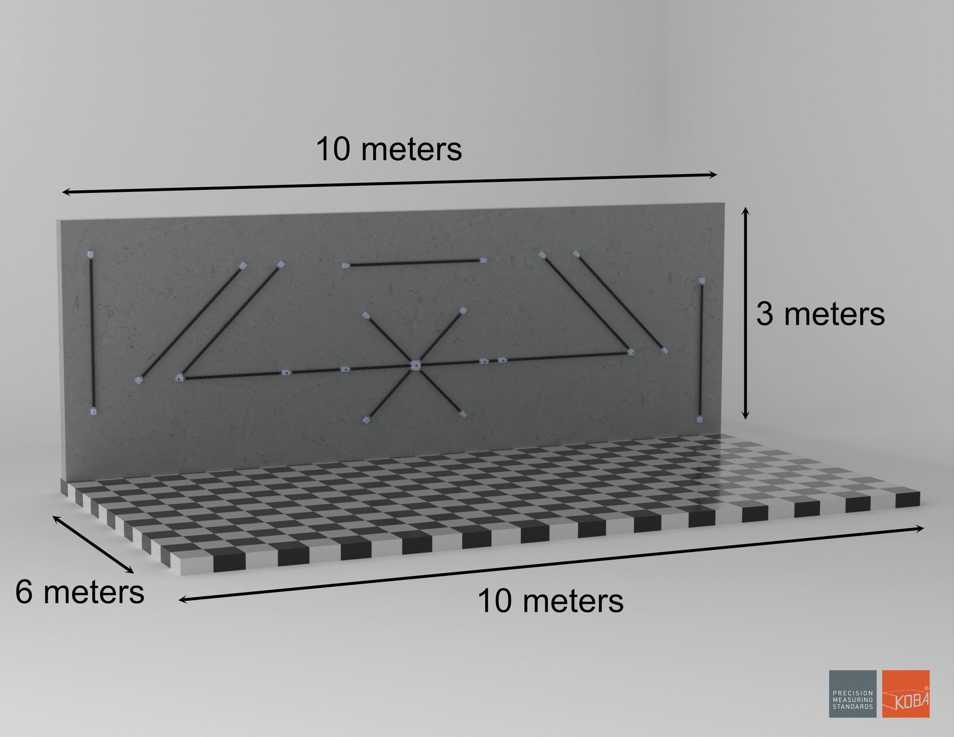
Figure 5: Rendering of artifact developed by Kolb & Baumann for the State Institute in Thailand. Photo courtesy of Kolb & Baumann.
According to Martin Wombacher, Technical Manager Head of DAkkS Laboratory D-K-15077-01-00 of Kolb & Baumann GmbH & Co KG, he suggests:
“The acceptance and calibration of laser trackers and tracers is a highly specialized topic. Suitable test specimens are calibration beams with 3-point holders (nests, with or without holding magnets), which must be calibrated according to the center distances when used with the 1.5" SMR. Various manufacturers offer standardized fixtures and reference beams with a maximum length of 2,300 mm. However, as these measuring systems are generally used for very large measuring volumes, acceptance or calibration with these relatively short reference bars does not fulfil the requirements of ISO 10360. This standard requires that the reference bar covers at least two thirds of the measuring volume diagonals. The Physikalisch-Technische Bundesanstalt has also installed a “calibration wall”, similar to the one they developed for the State Institute in Thailand, with a fixed arrangement of 3-point recordings. This artifact is approximately 10 x 3 meters in size, with a chessboard-like positioning area measuring 10 x 6 meters, in order to accommodate a wide variety of measurement volumes.”
Understandably some of the greatest minds are still hard at work and in the finest facilities in the world today. The search for perfection and accuracy continues at all levels and methods in the world of metrology. The future is just another adventure in the theory of relativity and “the fantastic network of a dream. (Albert Einstein)”
Sources:
- Linda Goodwin-Marino is Co-Founder/CEO of Paul W. Marino Gages, Inc and PWM Measurement and Standards. Located in southeastern Florida.
- Martin Wombacher, Technical Manager Head of DAkkS Laboratory D-K-15077-01-00 of Kolb & Baumann GmbH & Co KG, Aschaffenburg, Germany.
- All photos used by permission.