Computed Tomography
Inspection
NDT
By Udo de Vries
Industrial CT:
3D Inspection and Metrology for 3D Printing
CT inspection of the final part can check that the manufactured part exactly matches the initial 3D design, providing dimensional analysis and metrology of all critical internal dimensions.
Additive manufacturing (AM) probably represents the greatest paradigm shift in engineering manufacture since casting and the development of machine tools. 3D printing has allowed great strides to be made in parts design, rapid prototyping, and the production of complex components with integrated functions, which hitherto necessitated manufacture in separate machined parts. However, quality control and metrology are of supreme importance in this innovative technology, especially in those regulated industries where optimum functional performance and safety must be guaranteed. These tasks are precisely suited to 3D inspection and metrology in the form of industrial computed tomography (CT).

What Is Industrial Computed Tomography?
Industrial CT relies on the acquisition of a large number of 2D X-ray images and then reconstructing these to produce a 3D volume. In operation, this is achieved by placing the object to be scanned on a precision turntable within a closed cabinet and then subjecting the object to radiation from a high-power source of radiation. The object is rotated through 360° in small increments during this process. Radiation is absorbed by the object so that discrete 2D images are captured by a suitable detector. This 2D data is then volumetrically reconstructed, mathematically, to produce the CT volume.
Fan Beam vs Cone Beam
There are, traditionally, two techniques used industrially to carry out high-energy computed tomography on difficult to penetrate samples such as automotive large light metal castings or aerospace turbine blades. Both use the principles set out above, but they differ in the way that the beam of radiation is directed through the workpiece and the way that the data is detected.
Fan beam CT radiographs thin slices of the workpiece as it is rotated and moved linearly in discrete steps through the X-ray beam. The 2D radiography slices are detected by a collimated line detector and the individual slices are then reconstructed and combined to provide the full 3D volume. For a long time, this was the method of choice for high absorbing metal parts causing a lot of artifacts due to scattered radiation.
Cone beam CT uses a flat panel detector which completely captures the workpiece as it is rotated. The radiographic data is also reconstructed and combined to provide the 3D volume. As there is no need to step the sample through many discrete steps, all data is collected in just one rotation, hence cone beam radiography is much faster than fan beam CT - but less precise due to scatter radiation artifacts.
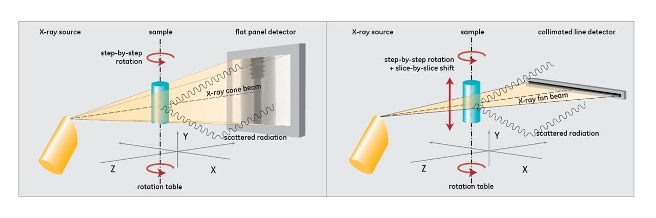
Fig.1 Cone Beam CT (left) and Fan Beam CT (right)
Meeting the Inspection and Metrology Challenges of Additive Manufacturing with CT
Simply stated, additive manufacturing uses modelling software to design and then produce physical three-dimensional parts by adding layer after layer of material. (This is the opposite of subtractive manufacturing, where material is machined out of a solid material to produce the designed part). There are various AM technologies and broadly, they can be stated as:
1. Sintering where metal or powder is heated by laser without being liquefied.
2. Melting of metal powders by laser or electron beam.
3. Stereolithography, where an ultraviolet laser is used on photopolymer resin.
Computed tomography can be used with all of these techniques at all stages of the additive manufacture, from the quality control of raw material to metrology of the finished part.
Getting the Right Powder
High resolution nanofocus CT imaging can be used to ensure powder consistency, such as the uniformity of particle size or shape and to analyze porosity and detect any foreign materials. Powder particles are very small, from a few micrometers to tens of microns. The size distribution of individual powder particles influences how the powder is compacted and affects the density of the build and can create visible defects later in the AM process. High resolution nanofocus CT allows detailed analysis of particle shape, size and volume distribution and this can help to determine the correct process parameters.
Fig 2 NanoCT Powder Characterization of a Titanium aluminide SLM capsule with nominal grain size 40-90 μm: automated colored particle size segmentation.
Getting the Process Right
CT can be used to identify any flaws which occurred during the layering process. The quality of powder and how it is spread during the build process could cause voids or material impurity within the structure. The shape, size and position of voids and flaws can be significantly affected by thermal stress in any subsequent heat treatment. Although the part may be in tolerance immediately post-build, any flaws can introduce significant distortion after heat treatment and part removal from the build plate. CT scans reveal size, location and distribution of flaws and help to optimize printing processes.
Precise Metrology of the Finished Part
CT inspection of the final part can check that the manufactured part exactly matches the initial 3D design, providing dimensional analysis and metrology of all critical internal dimensions, wall thicknesses and other features that may be difficult or impossible to measure with traditional nondestructive methods. Fig. 3 compares the 3D CT result of the as-built component to the as-designed CAD model to view color coded variation mapping. Latest high precision CT scanner reach reliable measurement accuracy of just a few micrometers.
Fig 3. Nominal / actual comparison of an additive manufactured aerospace reaction wheel bracket (DMRC / Volume Graphics)
Getting the Process Right
CT can be used to identify any flaws which occurred during the layering process. The quality of powder and how it is spread during the build process could cause voids or material impurity within the structure. The shape, size and position of voids and flaws can be significantly affected by thermal stress in any subsequent heat treatment. Although the part may be in tolerance immediately post-build, any flaws can introduce significant distortion after heat treatment and part removal from the build plate. CT scans reveal size, location and distribution of flaws and help to optimize printing processes.
Precise Metrology of the Finished Part
CT inspection of the final part can check that the manufactured part exactly matches the initial 3D design, providing dimensional analysis and metrology of all critical internal dimensions, wall thicknesses and other features that may be difficult or impossible to measure with traditional nondestructive methods. Fig. 3 compares the 3D CT result of the as-built component to the as-designed CAD model to view color coded variation mapping. Latest high precision CT scanner reach reliable measurement accuracy of just a few micrometers.
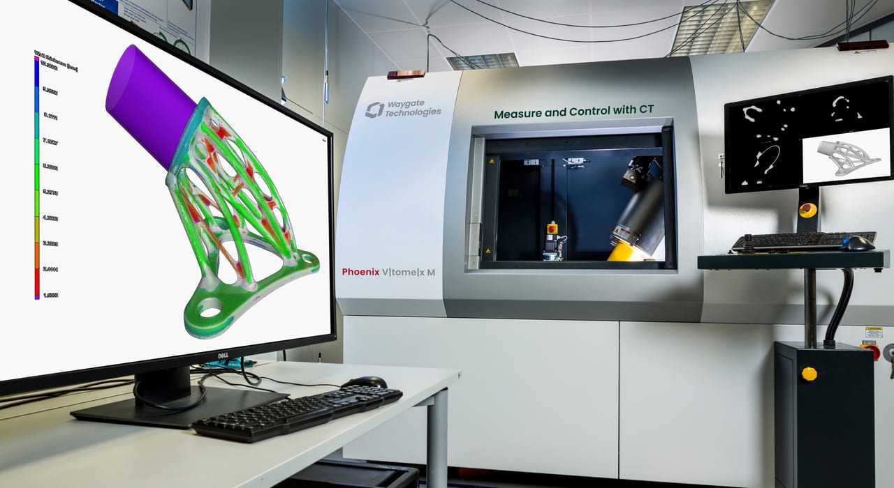
Fig. 4 A precision tomography machine
Perhaps the most important recent innovation has been the development of scatter correction, which allows high throughput cone beam scanning to be carried at a quality fast approaching that of fan beam scanning (see Fig. 1).
Due to scanning just one line per rotation, fan beam CT results are not affected by scatter radiation artifacts.
Cone beam CT is much faster since it uses a flat panel detector to take all required 2D X-ray projections necessary to reconstruct the CT volume in just one rotation. However, cone beam scanning is subject to X-ray scatter. X-ray scatter is caused by spurious X-rays, reflected from objects, such as walls, or deflected inside the X-rayed sample, which are outside the X-ray source–detector path, impinging on the detector and negatively impacting the CT quality by scatter artifacts.
The scatter correct technology is a proprietary combination of hardware- and software advances. Unlike former scatter reduction technology, which simulates scatter based on CAD data or the material properties of a workpiece, the new scatter correction technology really measures the scatter portion of the specific workpiece in the scanner and then digitally minimizes this from the CT result for every individual voxel. The application of scatter correct technology can reduce scan times from hours to minutes, compared with fan beam scanning.
Fig. 5 Comparison between scatter-corrected and conventional scans
In operation, two scans are performed by using proprietary scatter correct hardware. The software quickly compares the two CT volumes and automatically removes the artifacts caused by scatter radiation. This technological advancement provides image quality similar to that achieved with fan beam scanning but at speeds up to 100 times faster.
Filter technology is also available to mitigate the effects of beam hardening, which occurs when an X-ray beam is selectively attenuated when it passes through differing adjacent densities in the object being scanned, causing streaking of the X-ray image.
Other innovations which are helping to improve the efficacy of CT in additive manufacture include new detectors which provide high resolution images for easy detection of subtle indications and CT scanning software, which includes all necessary processing functions for control and calibration of the tomography system, acquisition of projection data, fast and optimized reconstruction of volumes, generation of geometrically correct surface data of the scanned object, and the execution of measurements with suitable software packages. In addition, high X-ray power can now be focused on a smaller focal spot to achieve doubled resolution imaging or doubled scanning throughput.
Looking to the Future
Additive manufacturing is still an evolving technology. It began as an idea in the 1980s and was first used to create parts from photopolymers using UV light. Various AM technologies have since emerged, allowing 3D printing to be used for metals as well as plastics. AM started with rapid prototyping, allowing the realization of complex designs of special parts and short runs of obsolete products. Today, it has reached the production floor, especially in the aerospace industry, allowing the creation of parts with an internal complexity never reached before. It takes no great leap of the imagination to see the technology eventually being used also in automotive, medical and production lines everywhere.
Computed tomography has kept pace with the developments in AM and already offers in-line machines which can be paired with automated robot loading to allow 100% inspection on the production floor.
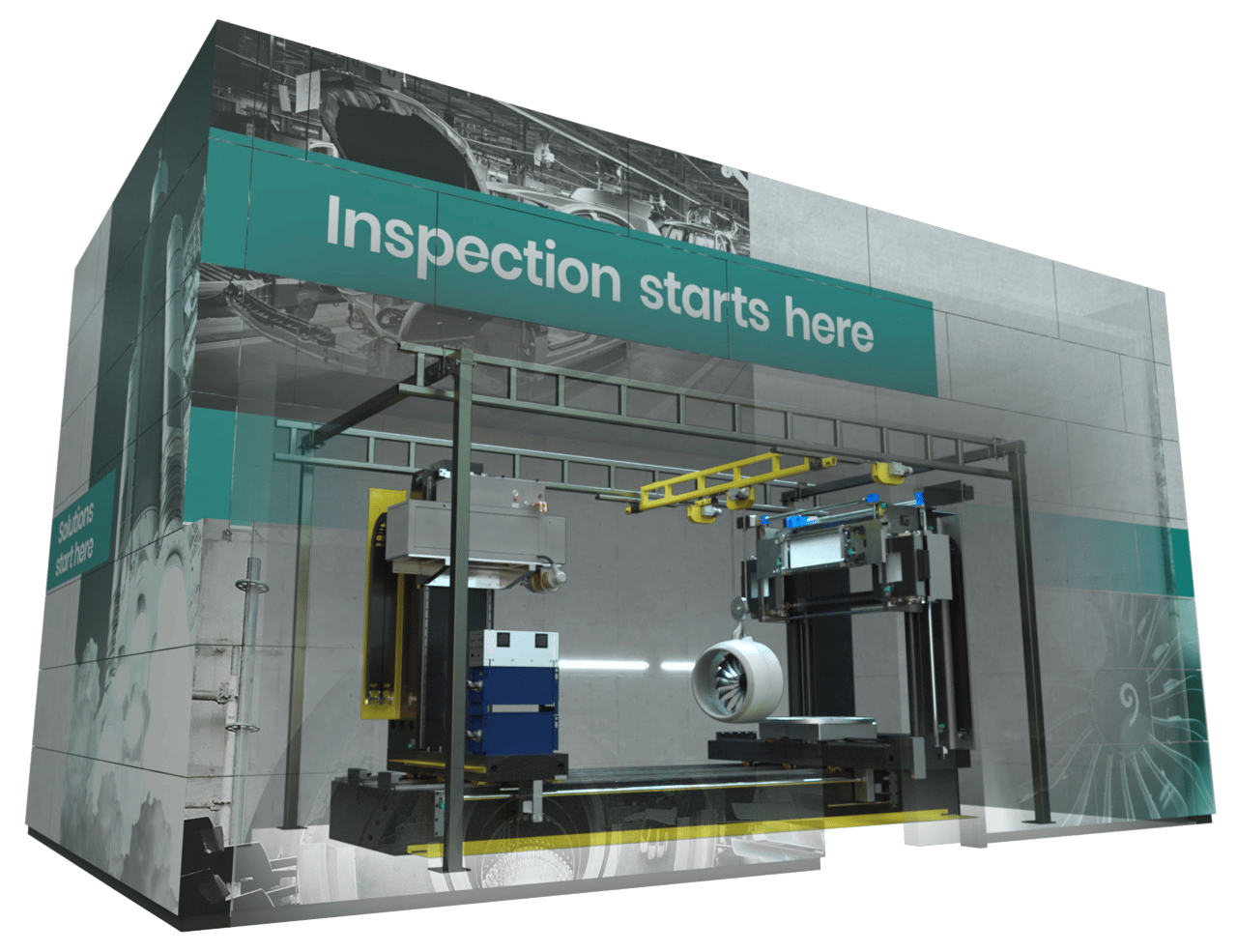
Fig. 6 High power CT systems enable even scanning of large and high absorbing AM parts with comparatively high throughput.
AM is also developing techniques to build larger parts and parts which use a mixture of metals of different densities. Inspection of these requires high power.
Conclusions
As additive manufacturing continues to grow in many industrial sectors, especially aerospace and automotive, industrial computed tomography (CT) will grow with it meeting the inspection and quality control challenges of today – and tomorrow.
Photo Source: © Waygate Technologies
Ian R. Lazarus is president and CEO of Creato Performance Solutions, providing leadership development, training, and solutions to support operational excellence.
Udo de Vries is Growth & Strategy Leader IXS at Waygate Technologies, a Baker Hughes business (formerly GE Inspection Technologies). For more information, email udo.devries@bakerhughes.com or visit www.waygate-tech.com.
Jim L. Smith has more than 45 years of industry experience in operations, engineering, research & development and quality management.

October 2021 | Volume 60 | Number 10

Scroll Down
Scroll Down