Linear Variable Differential Transformers (LVDTs) have emerged as a preferred choice for dimensional metrology applications in industries such as aerospace, automotive, semiconductor manufacturing, and general dimensional metrology. By Farzad Azimi, PhD.
Precision Gaging with LVDT Probes: A Guide to Understanding Key Performance Parameters
measurement
H2 Deck By Bold Name
h2 xxxxxx
H1 xxxxxx
h2 xxxxx
measurement
H2 Deck Info By Paragraph Style Bold
Headline
In today’s fast-paced manufacturing and quality assurance environments, handheld gages serve as indispensable tools for ensuring that components meet precise dimensional specifications. These instruments provide fast, reliable, and accurate measurements of a variety of parameters, including length, thickness, diameter, depth, and displacement. They come in various designs, such as dial indicators, micrometers, calipers, bore gages, and air gages, all of which are used to determine whether manufactured parts comply with tight tolerance requirements. Portability and ease of use make handheld gages ideal for use directly on the shop floor, eliminating the need for sophisticated setups or extensive training.
The evolution of manufacturing standards and the demand for tighter tolerances have driven significant advances in the design and functionality of handheld gages. While traditional models rely purely on mechanical means of measurement, many modern systems incorporate electronic sensors to improve accuracy, repeatability, and data collection capabilities. Among these, Linear Variable Differential Transformers (LVDTs)—highly accurate sensors widely used in applications where precision and repeatability are paramount—have emerged as a preferred choice for dimensional metrology applications in industries such as aerospace, automotive, semiconductor manufacturing, and general dimensional metrology.
Though LVDT probes are not handheld devices per se, they are frequently integrated into handheld or semi-portable gaging systems, thus combining the benefits of ergonomic use with electronic precision. These integrated systems now populate a wide range of applications, from digital comparators and bore gages to snap gages and custom inspection fixtures.
However, choosing the right LVDT probe for a given application requires a firm understanding of several technical specifications that define its behavior and performance. To make an informed decision, engineers, metrologists, and quality control professionals must understand key terms such as sensitivity, linearity, hysteresis, repeatability, and resolution. Each of these parameters impacts how the LVDT performs in real-world measurement systems.
For example, sensitivity describes the amount of electrical signal the sensor produces in response to a unit of physical movement. Linearity assesses how closely the sensor’s output tracks a perfect straight-line response. Hysteresis refers to output inconsistencies when the sensor’s core moves back and forth across the same position. Resolution indicates the smallest movement the system can reliably detect.
This article aims to introduce and clarify the fundamental terminology associated with LVDTs, particularly in the context of their use in precision measurement applications. The goal is to explain these concepts and provide practical insights into how each parameter influences the accuracy, stability, and suitability of LVDT probes for specific measurement tasks. Whether you’re selecting a sensor for a new inspection fixture or upgrading existing equipment, this foundational knowledge will help ensure that the chosen LVDT meets the operational and accuracy requirements of your application.
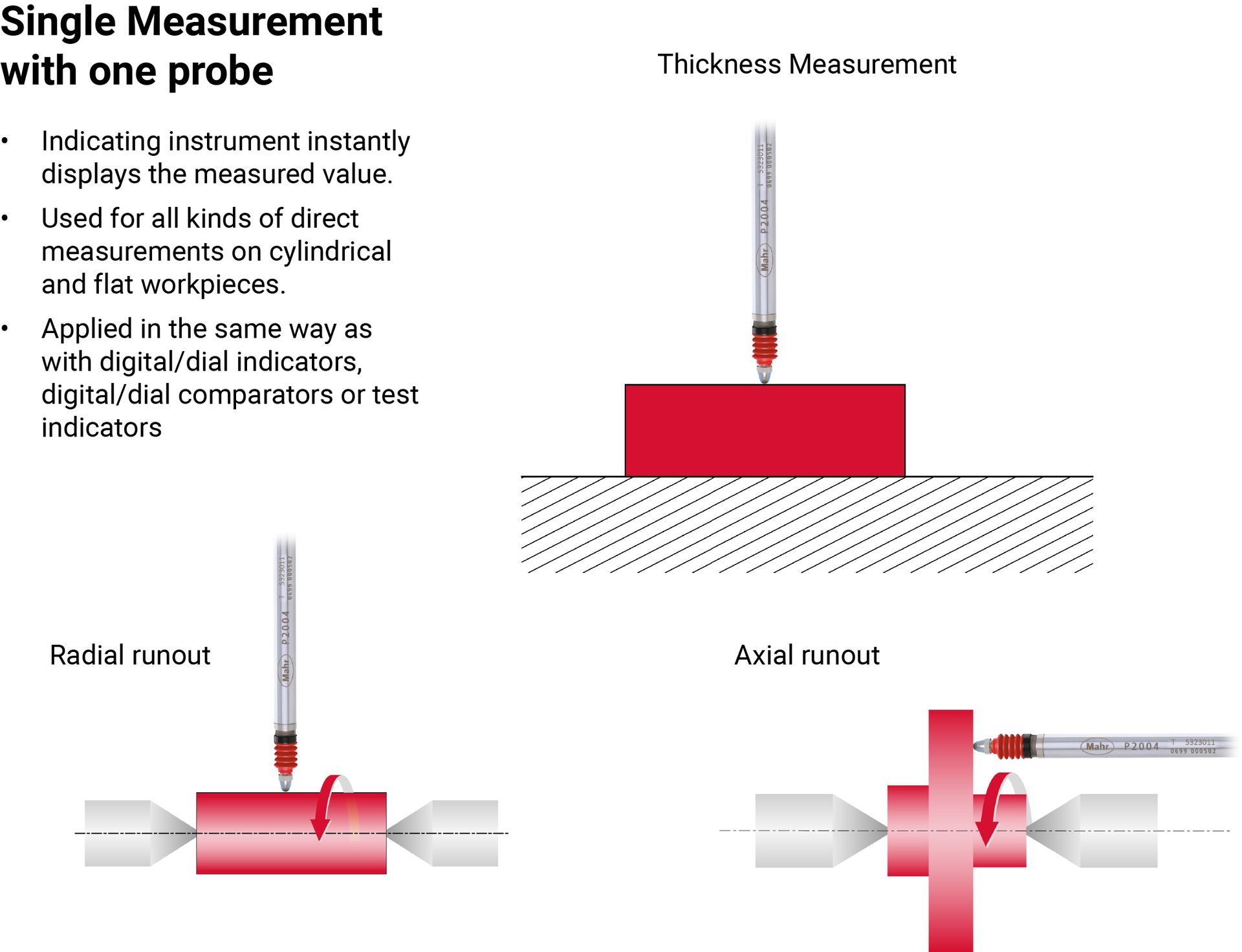
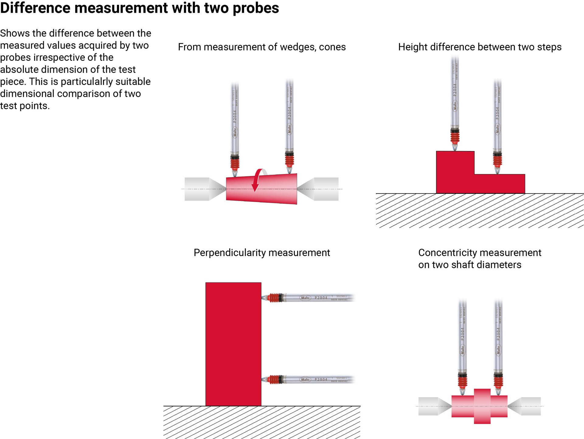
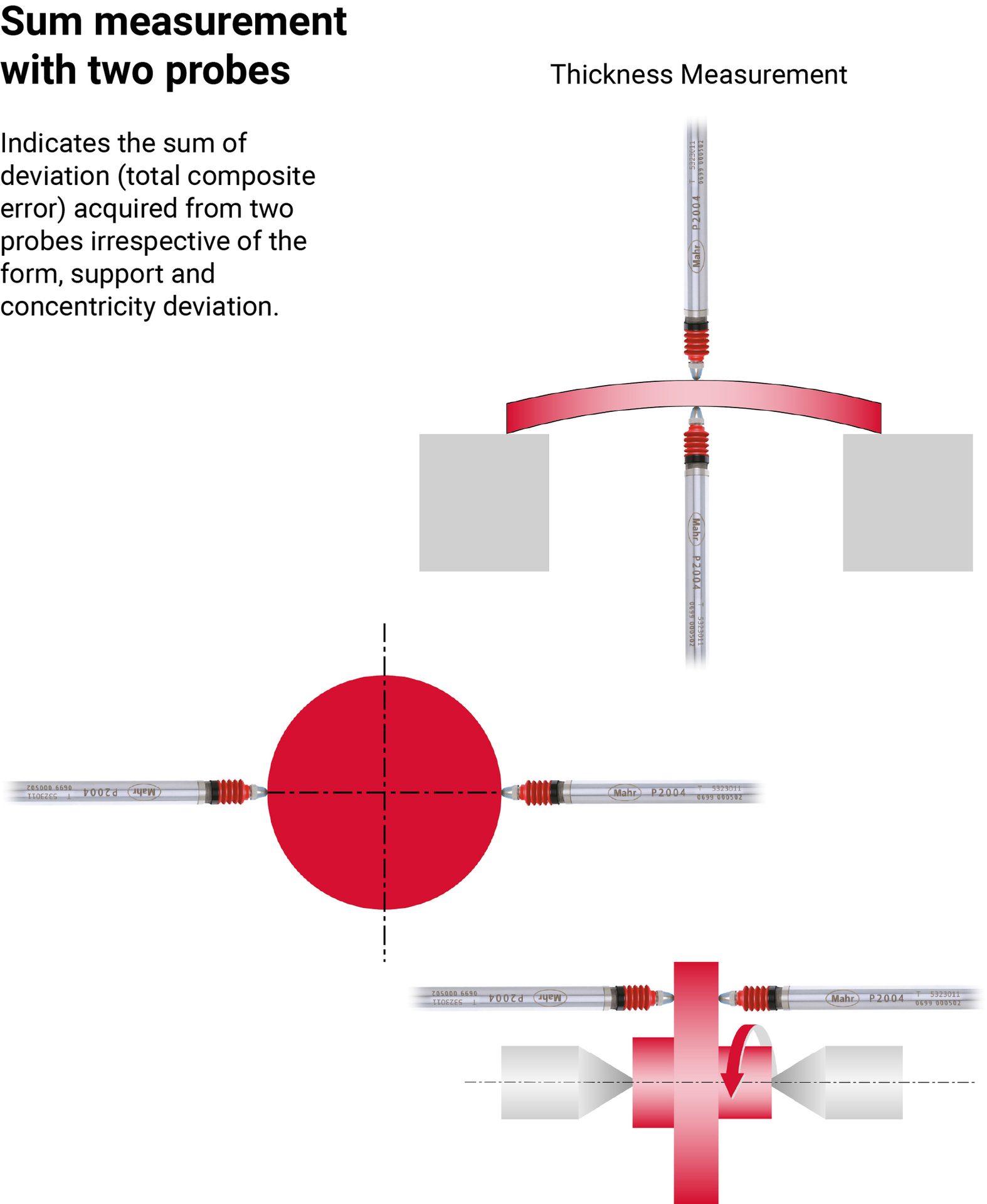
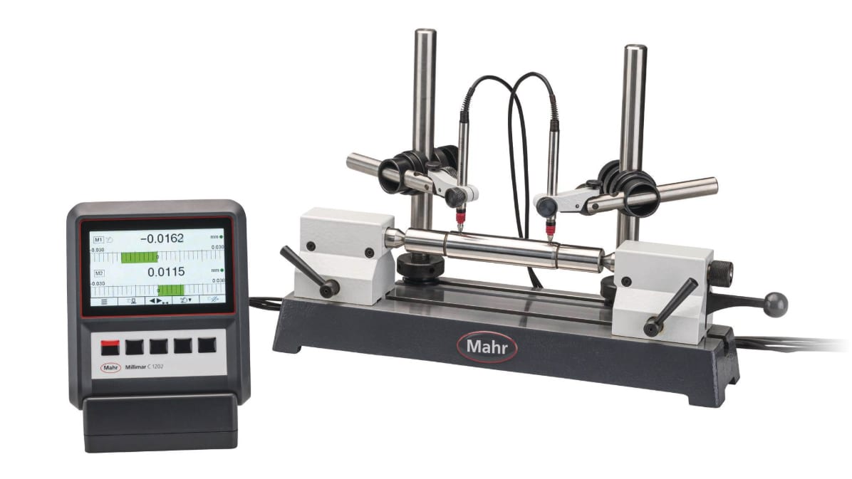
Figure 1 illustrates the application of LVDT probe configurations in various settings.
How LVDT Probes Work
The fundamental operating principle of an LVDT probe is based on electromagnetic induction. An LVDT consists of three coils wound on a hollow tube: a single primary coil and two secondary coils. A movable magnetic core is positioned inside this coil assembly. When an alternating current (AC) excitation is applied to the primary coil, it generates a magnetic field that induces voltages in the secondary coils. The position of the core determines the voltage differential between the two secondary coils. As the core moves linearly along the axis of the coils, the amplitude and phase of the output voltage change in a way that corresponds linearly to the core’s position.
A signal conditioner then processes the induced voltage to produce a DC or digital output proportional to the displacement. The result is a highly accurate, contactless position sensor capable of resolving displacements down to the sub-micron level, depending on the quality of the LVDT and associated electronics. The inherent linearity, robustness, and non-contact nature of LVDTs make them ideal for applications that require high precision and minimal mechanical wear.
Understanding Key Specifications of LVDT Sensors
To fully utilize the capabilities of LVDTs in precision measurement systems, it is crucial to understand several key specifications that define their performance. These include sensitivity, linearity, repeatability, hysteresis, and system resolution. Each of these factors plays a vital role in ensuring the reliability and accuracy of measurements, especially in environments where tight tolerances and high throughput are expected.
Sensitivity
Sensitivity in an LVDT refers to the ratio of the sensor’s output voltage to the mechanical displacement of the core, typically expressed in millivolts per volt of excitation per millimeter (mV/V/mm). It essentially indicates how much output voltage will be generated for a given displacement, normalized by the excitation voltage.
For instance, an LVDT probe with a sensitivity of 192 mV/V/mm will produce 192 millivolts of output for every volt of excitation for each millimeter the core travels. If the excitation voltage is 5 volts, a 1 mm displacement results in a 960 mV output signal. High sensitivity is beneficial as it enhances the signal-to-noise ratio, resulting in improved resolution and measurement accuracy. However, matching the sensor’s sensitivity with the signal conditioning electronics is critical. Excessively high output can lead to saturation of the amplifier or analog-to-digital converter (ADC), therefore compromising the linearity and accuracy of the system. This makes the selection of compatible components essential when designing an LVDT-based measurement system.
In applications where precision is paramount, such as inspecting high-tolerance aerospace components or critical medical devices, higher sensitivity enables the detection of minute dimensional changes that could impact product functionality or compliance.
Linearity
Linearity measures how closely the LVDT’s output corresponds to a straight-line function of core displacement. Ideally, a plot of output voltage versus displacement should form a straight line, indicating consistent proportionality. However, due to physical limitations such as imperfections in coil winding, magnetic asymmetries, and structural tolerances, actual output may deviate slightly from this ideal.
Linearity error is often expressed as a percentage of the full-scale output. A typical high-quality LVDT might have a linearity of ±x% full scale, meaning the maximum deviation from a perfect line is x% of the sensor’s total output range. This specification is critical in applications that require absolute measurement accuracy, such as in coordinate measuring machines or metrology-grade inspection stations.
While some degree of non-linearity can be corrected through software compensation using calibration curves or lookup tables, it is always advantageous to start with a sensor that exhibits high inherent linearity. This reduces reliance on external correction methods and ensures more stable performance across various operating conditions.
When using multiple identical LVDT sensors in a metrology system for applications such as parallelism, concentricity, or flatness measurements, one important consideration is the combined linearity of the system. When multiple sensors are used, the system’s overall linearity depends on how these individual errors interact with each other. If the linearity errors are assumed to be independent and uncorrelated, which is often the case when sensors are calibrated separately and operate in different positions, the appropriate way to estimate the system’s total linearity error is through the root mean square (RMS) method.
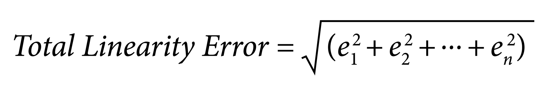
Where e1, e2, …, en are the individual linearity errors for each of the n sensors.
This provides a more statistically realistic estimate than simply adding individual errors, which would yield a worst-case. However, if the sensors’ errors are correlated or shift together due to shared influences (e.g., thermal expansion or structural alignment issues), the actual system error may be closer to the worst-case value.
Ultimately, the combined linearity of a multi-sensor system can be minimized through careful calibration, matching sensor characteristics, and compensating for systematic errors in software. Understanding and managing these combined effects is crucial for ensuring high measurement accuracy in demanding metrology applications.
Repeatability
Repeatability refers to the sensor’s ability to return the same measurement value under identical conditions. It is a measure of the sensor’s consistency and is particularly important in high-volume manufacturing and quality control environments, where repeated measurements are taken to monitor product conformity.
A sensor with excellent repeatability will produce the same output every time the core is moved to the same position under the same environmental conditions. This characteristic is especially important for tasks such as go/no-go inspections, automated sorting, and process control, where inconsistent readings can lead to costly errors or rework. Repeatability is influenced by mechanical stability, thermal variation, electronic noise, and the precision of the signal conditioning system. LVDTs used in precision fixtures often feature tight mechanical tolerances and robust mounting features to ensure that environmental or operational factors do not introduce variability in measurements. As such, selecting a sensor with proven repeatability is essential for maintaining confidence in the measurement process.
Hysteresis
Hysteresis describes the difference in the sensor’s output when the same position is approached from opposite directions. In a system with hysteresis, the output reading when moving from left to right may not exactly match the output when moving from right to left, even though the core passes through the same position. This can introduce ambiguity in measurements, especially in applications involving dynamic or bidirectional motion.
One of the key advantages of LVDTs is their minimal hysteresis, thanks to their non-contact internal design. The magnetic core floats freely within the coil assembly, with no physical contact to cause friction, backlash, or mechanical wear. As a result, LVDTs exhibit nearly zero hysteresis under ideal conditions, making them highly reliable for applications that require consistent bidirectional measurement, such as fatigue testing systems or actuator feedback loops. However, it is still important to consider factors such as mechanical mounting, cable routing, and environmental conditions, which can introduce minor sources of hysteresis even in LVDT-based systems. Proper installation practices and environmental controls help preserve the inherent advantages of LVDTs in minimizing this form of error.
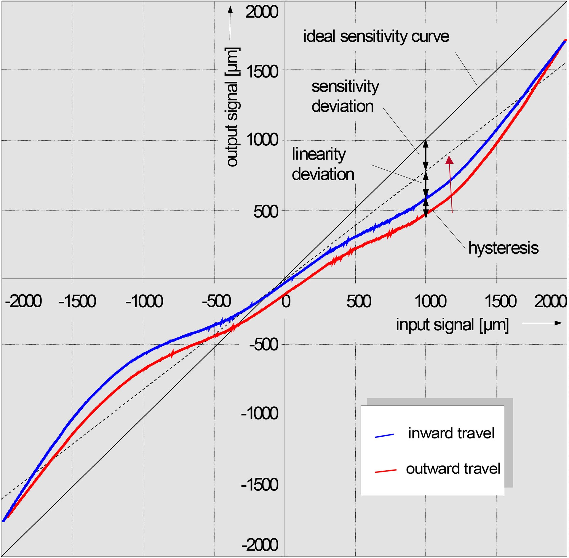
Figure 2 illustrates the sensitivity, sensitivity deviation, linearity deviation, and hysteresis. Note that this is only for illustration purposes and does not represent any real-world data.
System Resolution
Resolution is the smallest change in position that the measurement system can detect. It is determined by the sensitivity of the LVDT, the gain and noise characteristics of the signal conditioner, and the resolution of the ADC used to digitize the signal. High resolution is crucial in applications where fine measurements are required, such as semiconductor fabrication, microelectronics assembly, or high-precision machining.
Modern LVDT systems can achieve resolutions in the sub-micron range, particularly when paired with low-noise electronics and high-resolution ADCs. Maximizing resolution requires careful attention to system design. Signal conditioners must provide sufficient amplification without introducing noise or distortion. Shielded cables, proper grounding, and thermal management are also critical for ensuring that environmental factors do not degrade measurement precision. In some cases, resolution can be improved through averaging or filtering techniques, although this may come at the cost of slower response times.
Conclusion
LVDT-based measurement systems have become an essential component of modern manufacturing and quality assurance because of their robustness, precision, and adaptability. Although the probes themselves are not handheld, their incorporation into portable and handheld gaging systems has significantly advanced dimensional metrology by merging user-friendly interfaces with electronic precision. Understanding the key specifications of LVDT probes, such as sensitivity, linearity, repeatability, hysteresis, and system resolution, is essential for optimizing performance and ensuring that measurement systems meet the exacting demands of today’s manufacturing standards. Sensitivity affects the system’s ability to detect small displacements; linearity ensures accuracy across the measurement range; repeatability guarantees consistent results; hysteresis impacts measurement reliability under changing motion directions; and resolution determines the finest detail the system can measure.
By carefully considering these factors, engineers and metrologists can harness the full potential of LVDT-based measurement systems, ensuring accurate, reliable, and repeatable results for a wide range of applications across industries such as aerospace, automotive, electronics, and medical devices.