Your choice can be simplified by knowing what kind of information you need to collect. By Jacob Morales
Determining if
Force and/or Material Testing
is Right for your Application
Test & INspection
The majority of product testing in manufacturing environments requires the force measurement of samples to verify if they are able to withstand specific load application during post-production. However, throughout the product design and development stages, material properties are also tested and studied to determine if and how the material is an applicable fit for the product. There is a distinction between these two types of tests – force measurement and material testing - and your choice can be simplified by knowing what kind of information you need to collect.
The Difference in Units
First, it is helpful to understand the difference in units. Force testing measures the sample’s ability to withstand or fail under an applied load. These loads are commonly measured in values of pounds-force (lbf) or newtons (N), while height or travel is measured in distance units such as inches (in) and millimeters (mm). Material testing replaces the values of load and travel for stress and strain, which are typically measured in pounds per square inch (PSI, or lbf/in^2) or MegaPascals (MPa, or N/mm^2) for stress, and as a fraction or percentage for strain. The key difference between these two-unit sets is that stress and strain are determined from properties of the material sample itself, rather than just the load being applied.

Consider breaking a cube in half in a uniaxial force tester operating in a perfect system where objects don’t deform under tension. The test is designed to hold the sample by opposing faces, applying a tensile force to break it in half. The resulting halves would be perfect square prisms, each half the height of the original cube. A force test assumes that the size and shape of the cube is irrelevant – either because all of the cube samples are uniform in dimension so that the size and shape would not matter, or the difference in sizes are unimportant as long as the cube reacts properly to the loads being applied. As a result, it would be unnecessary to test in values of stress and strain and instead measure in load and distance.
A material test, however, requires knowing the dimensions of the cube to properly report its findings. Let’s assume the cube is one inch in length on each edge, and it takes 100 pounds of force to break the cube in half. For a force test, the 100 pound-force value is all that’s required for the force system to collect as a data value, but for a material test the system needs to translate that information to PSI. Because it is a perfect cube breaking evenly in half (without stretching), the cross section is one inch by one inch square. To determine the stress at break, the 100 pound-force is divided by the cross-sectional area of 1 square inch, which equals 100 pound-force per square inch, or 100 PSI.
To help put this into context for factoring in variables when material testing, let’s think of a cube with two-inch edges, made of a different material that also breaks at 100 pounds-force. Now that the cube is bigger, so is the cross-section, which is now two inches by two inches, or four square inches. When dividing the 100 pounds-force by that area, the result is 25 PSI. It is a lower stress value – an indication of a generally weaker material. Consider that the area where the break occurs on the second cube is four times the area of the original, but still breaks at 100 pounds of force. If you had a cube of the second material that was one inch on each side like the first one, you can assume that it would break at a lower load value. You can even estimate that value: 25 PSI times 1 in2 is equal to 25 pounds. Operating with that same information, you can determine that the second cube, being two inches on each edge, would have a breaking load of 400 pounds-force; 100 PSI times 4 in2 equals 400 pounds.
The example provided ignores many real-world behaviors for the sake of simplicity, but the general application is the same -- material tests determine the inherent properties of what is being tested, and need to be scaled appropriately for when the samples change size so that they collect information accurately. A force test does not require that information, and can note behaviors under load without needing the material sample test data. Looking at the first test example again, the test goal could be that the sample needs to break before exceeding 100 pounds of force to pass the test. The second material would pass as a one-inch or two-inch cube, but the first would only pass as a one-inch cube, because a two-inch cube would require four times the load to break.
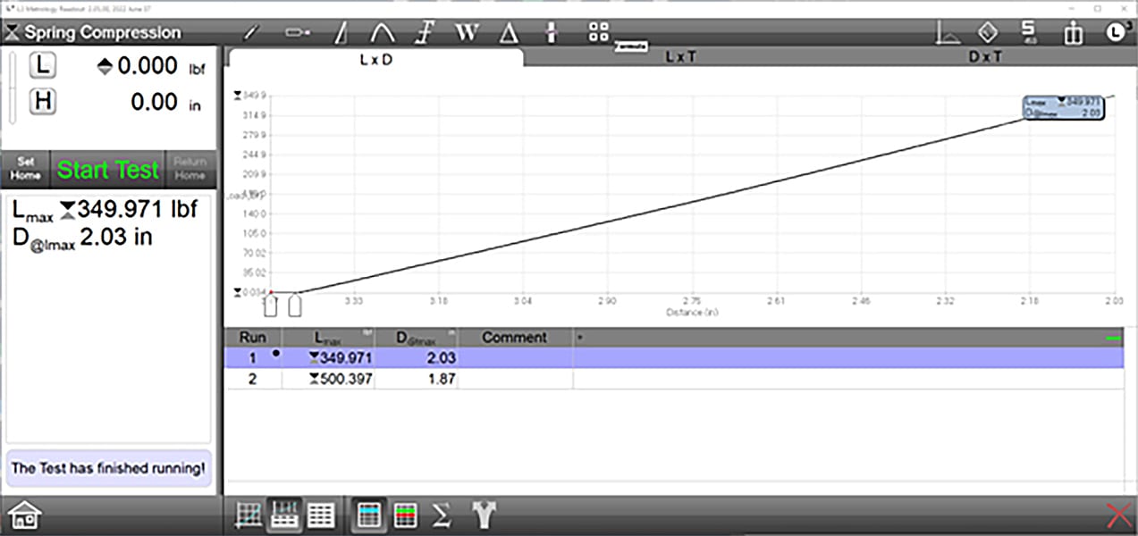
A spring compression (load) test. The spring follows a linear compression and reaches a maximum load at approximately 350 pounds for one sample, and 500 for another. Pressure testing is not required for this test, and elongation is not calculated, so the stress/strain values are not graphed.
Force Testing Examples
One of the better examples of a consistently manufactured product that must conform to specific force application and displacement standards are wire coil springs, made for either tension or compression. When testing, the springs are most often checked to see if they either extend or compress to the appropriate distance to determine their spring rates (in units of force per distance such as LBF/in, or N/mm) meet with the design requirements. Because of the consistency in their design, there’s not much of a need to determine the material properties of the spring. They are not expected to break under tensile or compressive load applications because their design is intended to ensure a return to their original length, or free length. Material testing is more appropriately performed on the raw wire or metal samples, rather than performing the material calculations for the fully formed spring.
In the case of springs, force testing often takes the form of testing an item’s functionality instead of its material properties. Take, for example, the need to test a button or a switch. The manufactured parts typically have uniform designs, so the testing of a minimum required force rather than stresses across the component surface is simpler to perform. Other examples include syringes for both plunger testing and puncture testing, as well as packing material for strength – either for bubble wrap or air bag packaging to test for minimum popping force, or foam compositions for breaking strength under load.
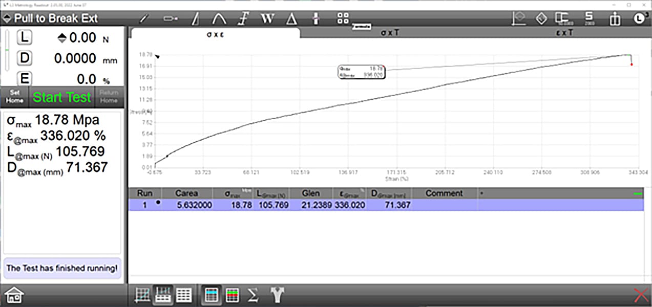
A material test progressing to sample break, determining the maximum stress (σmax) and the strain value at that point (ε@max). A cross-sectional area and gage length was provided for the controller to calculate the stress from the load and the strain values. The Load at Maximum Stress (L@max) and travel distance at that point (D@max) are calculated from these values.
Material Testing Example – Wire Testing
Building on the testing example of a spring, consider that the metal properties of the spring’s uncoiled wire can be assessed through the analysis of stress-strain testing. Unlike when in its coiled form, the lengthwise testing gives an easier means to determine the cross-section upon which the stresses are applied, which is equal to the area of the circle defined by the wire diameter. It also allows for proper measurement of the elongation, as it occurs along the sample’s whole length where appropriately gripped.
Using a wire instead of the coil spring provides an additional advantage. In environments where high precision is required, an elongation measuring tool called an extensometer can be used. These devices are designed to grip the samples at fixed points, and measure the change in distance between two points as the sample stretches. For example, if an extensometer has grips with an initial separation of one inch, and the sample stretches to further separate them by an additional half inch, the recording of the test will note a fifty percent increase of sample length, or elongation. The design of the extensometer often takes into account the intended sample material, and are constructed with physical limits to their maximum travel distance.
Depending on the extensometer, these travel limits might be shorter than the full length of a test stand, but well within the expected limits of elongation based on material ductility. Integrated extensometer units have the advantage of being able to operate with the test system’s software, while independent units can be specifically configured for the material type. For example, longer elongation devices may be used for highly ductile samples, and more durable models are appropriate for less ductile samples so that they can stay on the sample through its break.
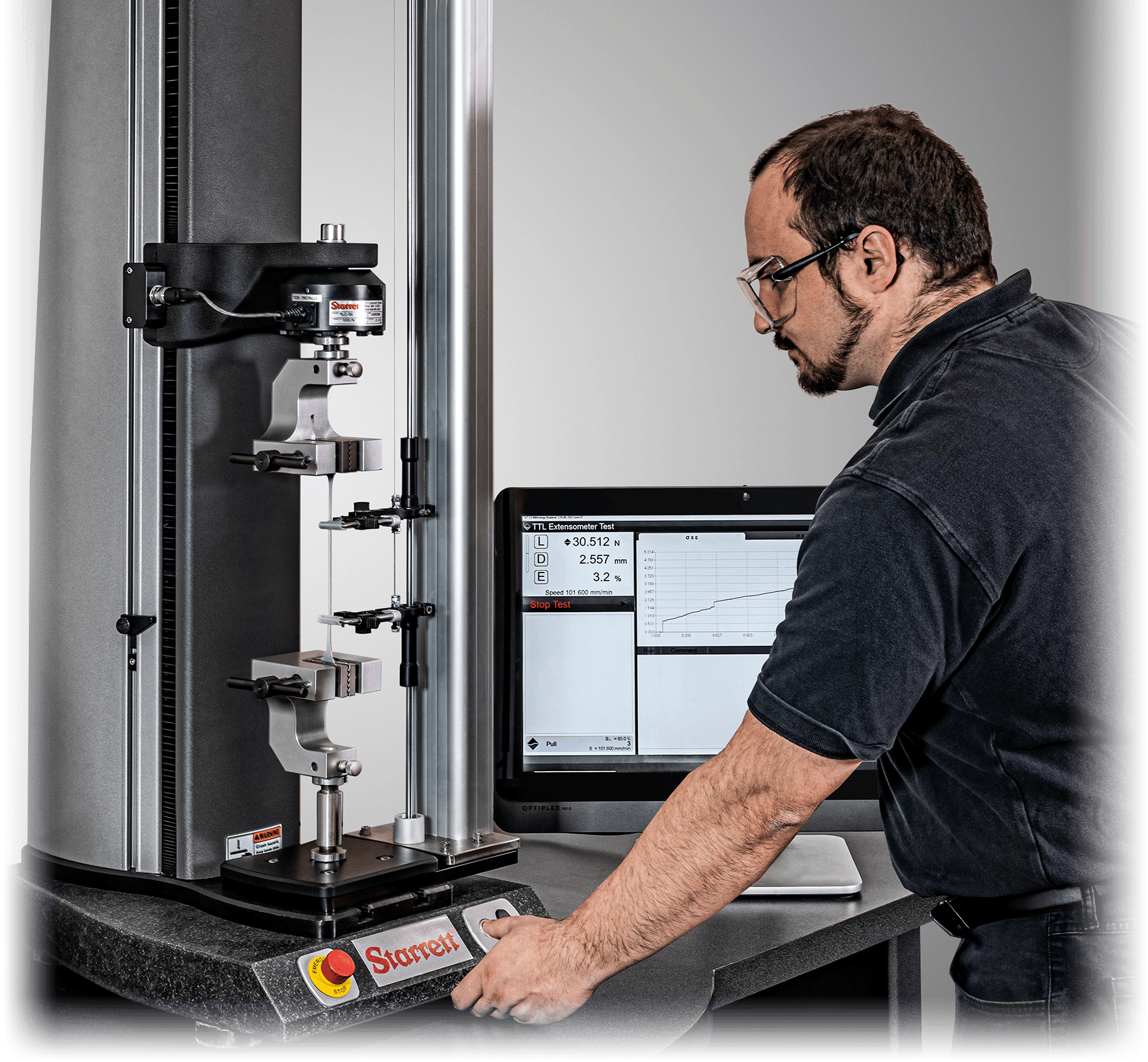
Photo Source: The L.S. Starrett Company
Jacob Morales, technical support – Starrett Force Equipment, The L.S. Starrett Company. For more information, call (978) 249-3551 or visit www.starrettmetrology.com/force.
March 2023 | Volume 62 | Number 3