Quality 101

If you take care of your gages, they will take care of you and the parts you manufacture. By Mike Oddy
Taper Pipe Thread Inspection, NPT
Taper Pipe Threads are one of the more challenging threads to produce and measure. The ASME B1.20.1-2013 Pipe Threads, General Purpose (Inch) is the current standard that covers both the part thread specifications and the gages for NPT, NPSC, NPTR, NPSM and NPSL threads. We will be focusing on the National (American) Standard Pipe Taper (NPT) threads. Generally, NPT taper pipe threads are a 60° thread form that is tapered at 0.75 in / ft. (1°47’ half angle). The taper causes the rules for Go and No-Go gage inspection to change as compared to straight threads. To understand the gages, we must first understand how the part threads work and their purpose.
NPT part threads have a tapered internal thread that assembles with a tapered external thread. Per the ASME standard, “The mating threads should always contact on the thread flanks. The design tolerances are such that mating crests and roots may clear, contact, or interfere. This joint may not necessarily seal, unless a sealant is used. ” (See the ASME B1.20.1-2013 for the illustrations of the root and crest clearances.) If you require a pressure tight seal, a sealant must be used on the wrench-tight length (L2 external and L3 internal).
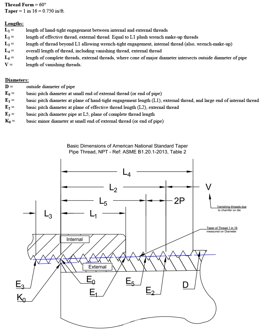
The Illustration in Fig. 1 shows the basic thread form of the hand tight (L1) part assembly of internal and external threads. This includes some of the definitions as stated in the ASME standard.

Figure 1
The Fixed Limit gages for the NPT thread form are L1 thread plug and ring gages. The L1 thread plug and ring gages inspect the L1 length of engagement of the internal and external NPT part thread. The inspection is done as a reference to a calibrated pitch diameter at a specific length on the tapered thread. This pitch diameter at the L1 length is shown above as E1 in Fig. 1.
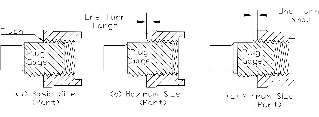
NPT L1 thread plug gages have a Basic notch ground to the E1 pitch diameter at the L1 length. The internal part thread is considered in tolerance if the notch on the gage is within +/- 1 turn from the face (Flush) of the part thread. (See Fig. 2)

Figure 2
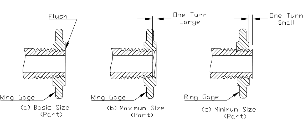
NPT L1 thread ring gages do not have a notch. The thickness of the ring equals the L1 Basic length. The large end of the ring equals the E1 pitch diameter. The external part thread is considered in tolerance if the small end face of the NPT L1 ring gage is within +/-1 turn of the small end of the part thread. (See Fig. 3)

Figure 3
The above illustrations show a part thread with the thread being full to the end of the part. Many pipe thread parts are manufactured with chamfers or counter bores. These require minor exceptions to the visual location of the notch on the NPT L1 plug or the small end face of the NPT L1 ring. (See ASME B1.20.1-2013, pg. 12 Para. 3.2.4.)
- If the external threads that have a chamfer diameter smaller than the minor diameter or internal threads with a chamfer diameter larger than the major diameter, the reference point will be the last thread scratch.
- If the external thread chamfer diameter is equal to or exceeds the minor diameter or an internal thread has a chamfer equal to or smaller than the major diameter, the reference point is the end of the fitting or pipe.
The NPT L1 ring and plug gages do not inspect the L2 or the L3 (wrench tight) lengths of engagement for the NPT threads. The ASME B1.20.1-2013 states, under paragraph 3.2.7, “Supplemental Gaging,” “Conformance to this standard requires that all basic design dimensions be met, (within applicable tolerances), including taper, thread truncations, lead, and flank angle over the L2 and L3 lengths.” The L2 & L3 part threads may be inspected using optical methods in conjunction with measurement and control of the cutting tools.
Be careful using gages from other gaging systems, such as ANPT per SAE AS71051B or NPTF gages per ASME B1.20.5. While many of the basic dimensions are the same, the tolerances and truncations may not be. Use of gages from other pipe standards requires an in-depth knowledge of what the gages are actually inspecting and how these differences will affect the parts being inspected. Gages like the ANPT Crest Check (6 Step) truncation gage may be used to check the truncation limits of an NPT thread. Both the ANPT and the NPT part threads have the same truncation limits. It is important to note, the ASME B1.20.1-2013 does not approve or mention the use of the ANPT Crest Check truncation gages to inspect NPT threads. As with all Supplemental Gaging, both the part manufacturer and the customer must agree on the use of all supplemental gages prior to manufacturing the NPT part threads.
Plated threads pose another challenge to inspect prior to plating. In many cases you will not need a special gage to inspect pre-plated pipe threads. You may use a standard gage and calculate an adjusted stand-off to the notch of the plug or the small end face of the ring. See paragraph 3.2.6 in the ASME standard for more information. Custom gages may also be made if needed.
In closing, we need to briefly discuss the inspection or calibration of the NPT L1 plug and ring gages. Many labs and gage users prefer to inspect or calibrate NPT gages with NPT master gages. This works well if the working gages are ordered and made to a matched set of master gages. It is important to note, a working L1 plug or ring gage is not a master gage. Master Ring and Master Plug gages require the following tolerances per paragraph 7.2.1 in the ASME B1.20.1-2013. “Master gages should be made to the basic dimensions as accurately as possible, but in no case shall the cumulative variation exceed one-half of the total cumulative tolerance specified in columns 13 and 14 of table 9.”
As with any tool, understanding how it works and what it does are critical to making in tolerance parts. If you take care of your gages, they will take care of you and the parts you manufacture.

