When a force measurement and material test system is optimally designed for the application at hand, the solution will provide the desired results. By CW Moran
Specifying a Force Measurement and Material Testing System to Suit Your Application
measurement
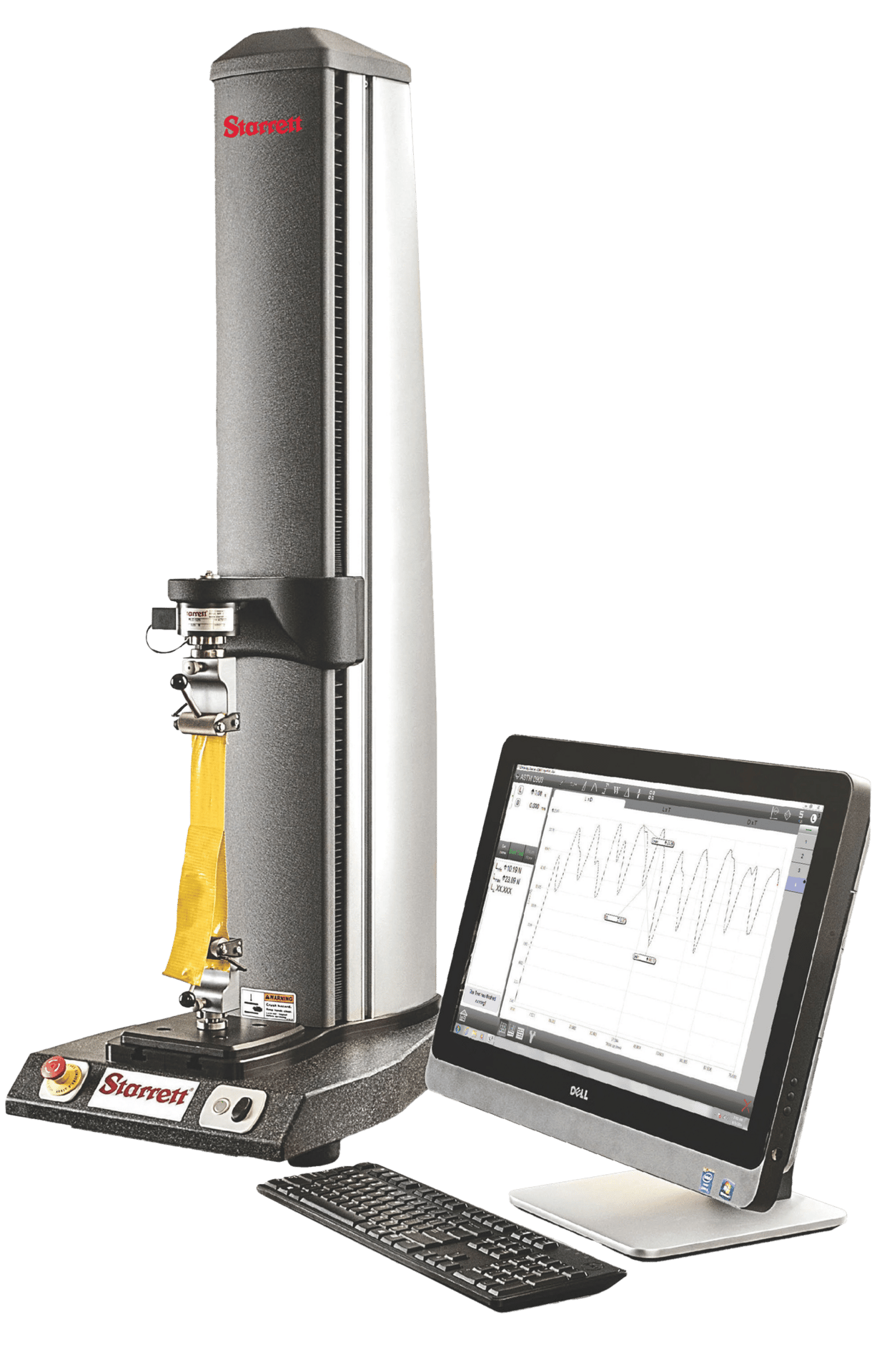
Ideal for compression and tension testing, force measurement and material test systems are offered with a combination of components to fit virtually any application. Regardless of application, each has the same basic components: a test stand, software, a load cell, and a fixture. This article provides a primer on how to simplify the selection and specification of a force measurement and material test solution.
H2 Deck Info By Paragraph Style Bold
Headline
System Composition
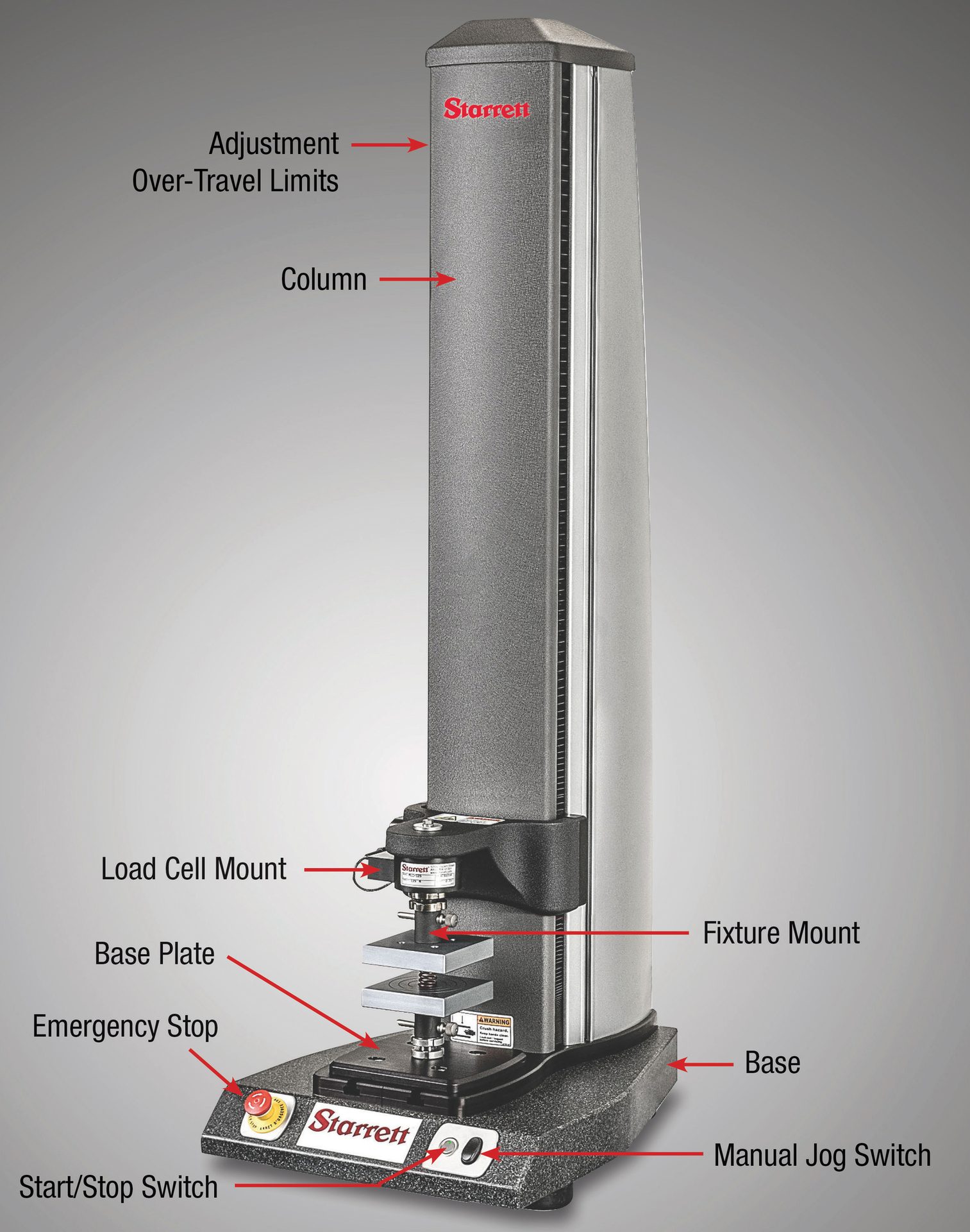
The test stand performs the movement in a tension or compression test. It is controlled by the software and tablet or PC interface, or with optional handheld force gages for entry-level stands. Test stands should be constructed from the highest quality materials, providing maximum stability, accuracy and repeatability. Easy-to-use, accurate test stands come in a wide range of sizes and travel options, depending on application requirements.
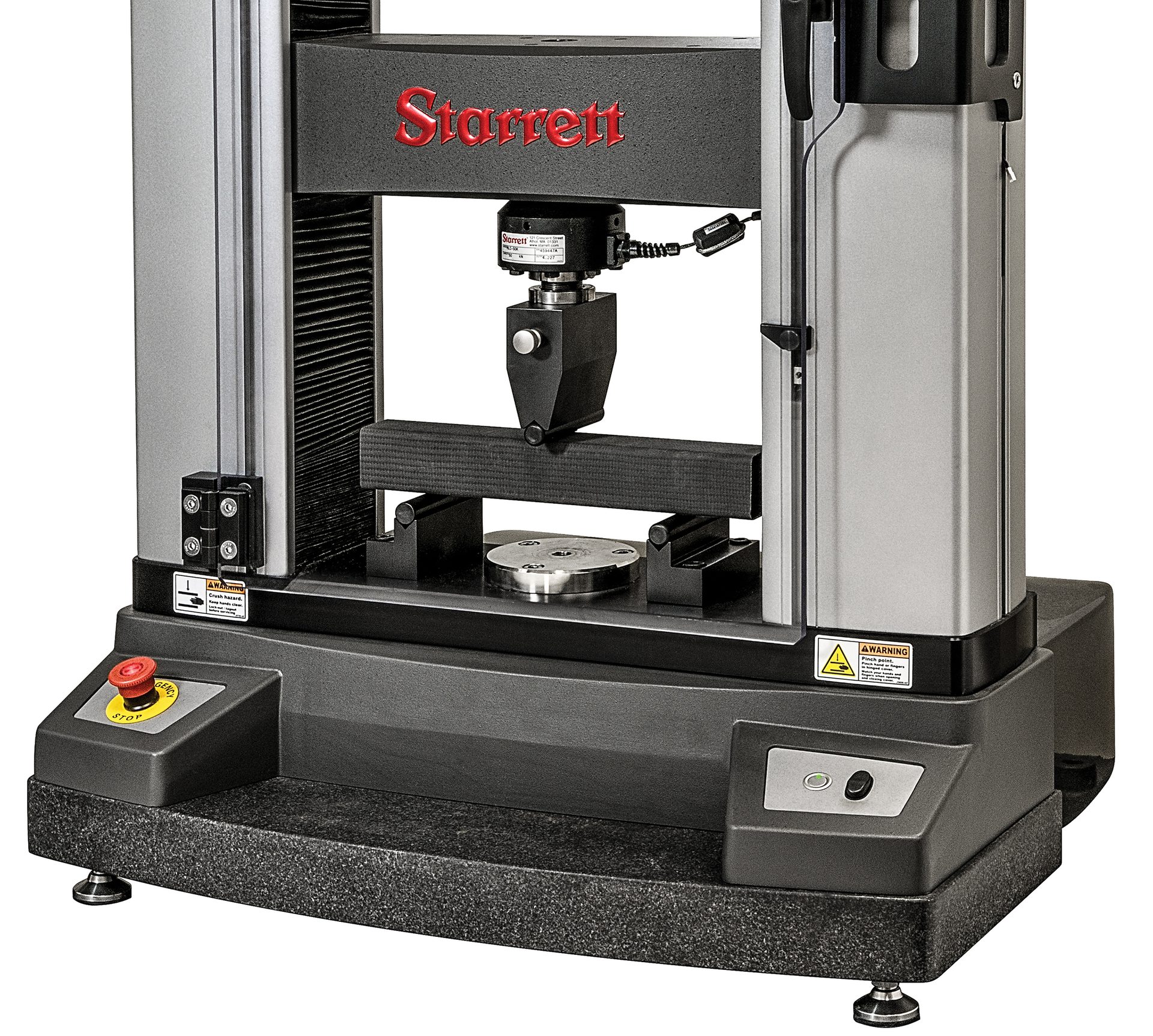
Test stands have multiple levels of load capacity and travel, depending on the model and user needs. Compact economical stands are ideal for quick checks for incoming or in-process inspection. Larger, more robust stands are ideal for simple load, distance, and break applications as well as more complex material testing applications such as tensile strength, stress or strain. Dual column test stands are available for higher load capacity force and material testing applications.
Software Options
There are a number of different software options available for quality control and incoming inspection, depending on the type and complexity of the tests being conducted.
1. Engineered to meet the requirements for fast, efficient, and high-volume testing, Entry-Level software is ideal for
• Load Limit Testing • Distance Limit Testing • Break Limit Testing • Cyclic Count Testing • Cyclic Duration Testing • Constant Load Testing • Constant Distance Testing
2. Enhanced software for quality and engineering personnel offers capabilities for demanding force measurement testing. Users can create complex test methods or use standard templates provided in the software, and perform the following tests:
• Tension Testing • Compression Testing • Flexural Testing • Cyclic Testing • Shear Testing • Rate Control Testing • Friction Applications • Coefficient of Friction Testing • Spring Testing • Peel Testing

3. Optimized material test software is also available for users involved with material testing and characterization such as research engineers, design engineers, quality control technicians, and test technicians. This software is capable of performing all the same functions as the entry-level and enhanced software described previously in this article, and also enables the advanced testing of material properties, such as Young’s Modulus or ultimate tensile strength. This software can be used for:
• Stress Testing • Strain Testing • Elongation Testing • Strength Testing • Measure Offset Yield • Measure Modulus: Elastic, Chord, Tangent • Measure Energy, Work and Resilience
Load Cells
Precision load cells are required on every test stand for force measurement, force analysis, and material testing applications. A load cell is a type of strain gage and is the part of the system which measures the amount of force being applied during a test. There are different load cell formats, depending on test stand selection. Every type of load cell also comes in a range on load capacities to meet diverse application requirements. There are three main types of load cells, depending on the test stand being utilized, the type and complexity of tests being conducted and the environmental conditions the test system will encounter:
- General-purpose load cell sensors that are full-bridge, temperature compensated, strain gage instruments are designed and optimized for basic force testing applications. These S-beam sensors feature high axial stiffness and minimal deflection at full capacity which leads to improved measurement accuracy. These sensors are available in load capacities from 2lbf-500lbf (10N-2500N).
- Also, general-purpose load cell sensors that are full-bridge, temperature compensated, strain gage instruments are available that are designed and optimized for material testing applications. These low profile sensors feature high axial stiffness and minimal deflection at full capacity which leads to improved measurement accuracy. These sensors are available in a load capacity range of 28lbf-11,250lbf (125N-50,000N).
- Another option includes load cell sensors that are full-bridge, temperature compensated, strain gage instruments that are designed for force measurement applications, and are also suitable for some material testing applications. These S-beam sensors feature high axial stiffness and minimal deflection at full capacity which leads to improved measurement accuracy. They are available in three configurations including “Economy” for most general purpose force measurement applications. “Sealed” S-beam Sensors are a good choice for applications in non-laboratory environments where dirt, oil, dust and debris may be present. “Premium” S-beam Sensors are ideal for low load applications, and feature a safe overload rating of 1000% of the sensor’s load capacity.
Fixtures
The largest category of options for any test stand system is the fixtures. The sheer volume helps to ensure that there is an appropriate solution for virtually any application. Here is a summary of some of the available fixture options:
- Platens: Made for aluminum or steel for compression applications. Available in fixed or self-leveling for soft samples.
- Vise-Action Fixtures: A very easy sample loading option. Jaw faces come in multiple sizes and surface finishes.
- Rope and Bollard Fixtures: For testing rope, cable, filaments, yarn and more. Designed for proper sample alignment.
- Flexural Fixtures: Used in 3 and 4 point bend testing. A flexible testing solution with adjustable spans.
- Force Gage Adapters: Used to mate dissimilar threaded connections. Available in male-to-male or male-to-female.
- Eccentric Rollers: An excellent self-tightening fixture for flat materials that deform under load.
- Wedge-Action Fixtures: Designed for easy loading and alignment. Available in multiple jaw face finishes.
- Button Fixtures: Designed to test the tensile strength of electrical connectors that are crimped onto wires.
- Peel Fixtures: Suitable for determining adhesive strength. Fixed 90 degrees and adjustable models available.
- Extensometers - Used in conjunction with material testing software. Long travel options are available.
- Pneumatic Fixtures: Ideal for high volume testing and maintaining a consistent clamping pressure.
- Spring Test Fixtures: Ensure correct alignment for accurate measurement of spring constants, tension, and length.
- Syringe Test Fixtures: Designed to make loading and unloading easy, fixtures test tension and compression.
- Scissor Fixtures: Self-tightening grips with a large variety of jaw faces available, great for elastomers, plastics, and more.
- Coefficient of Friction (COF): Meet ASTM, TAPPI, and ISO application standards for determining COF.
- Food Texture Fixtures: Measure food characteristics such as shear, brittleness, softness, crispness, and more.
- Hook Adapters: A good general purpose option available in clevis and threaded mounting options.
- Clevis Adapters: Used to secure most testing fixtures available. Provides quick and easy swapping of setups.
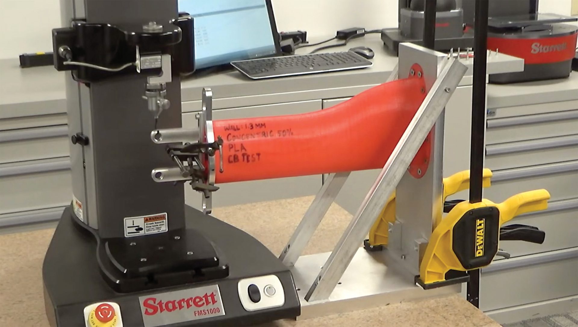
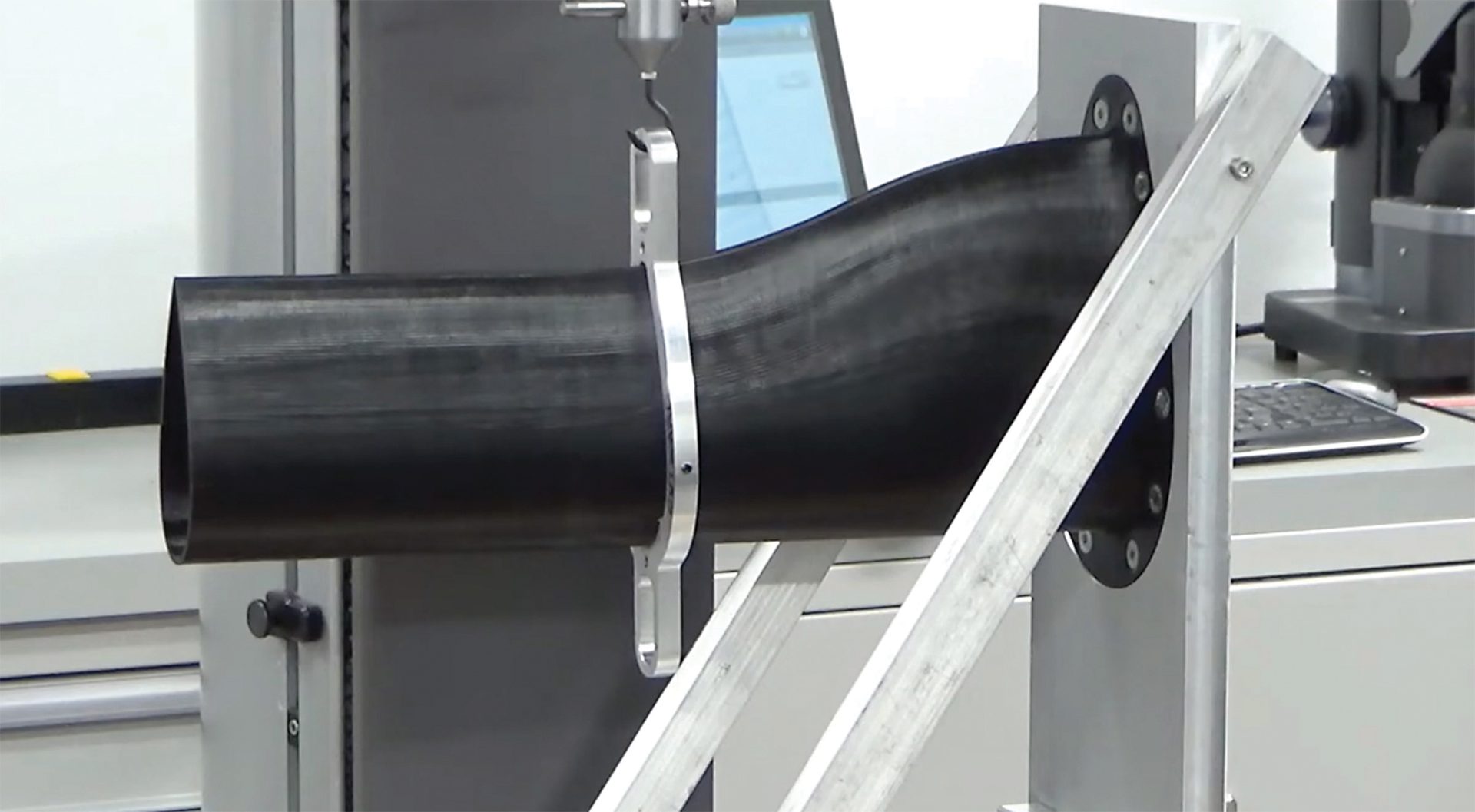
Starrett FMS 1000 test stand with a 500N load cell and L2 software setup to test the structural capacity of custom profile stings during high-threshold testing in a wind tunnel.
Test 1 – testing the center of pressure of the sting.
Test 2 – testing three inches off the end of the sting.
When a force measurement and material test system is optimally designed for the application at hand, the solution will provide the desired results. Here is an example of a successful design to force test profile stings:
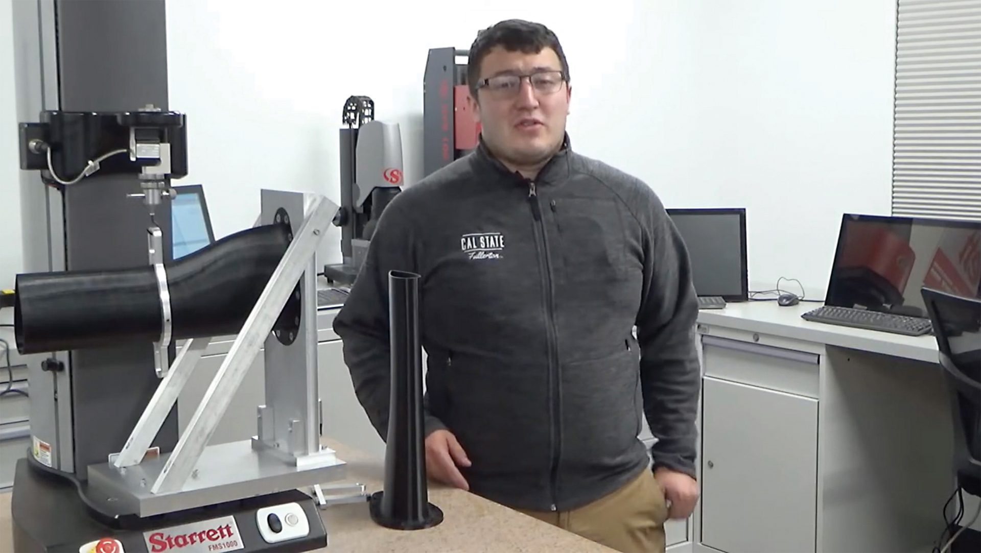
A group of graduate students was conducting research in the field of ground vehicle aerodynamics to test the structural capacity of custom profile stings during high-threshold testing in a wind tunnel. The stings were mounted to the top face of the wind tunnel and used to consolidate cabling and actuating rods for a kinematic system. The system served to propagate a test vehicle model in six degrees of freedom where the stings were subjected to forces being applied to the leading edge, perpendicular to its length. The stings were made from 3D printed material with wall thicknesses of 0.03" (0.8mm), 0.04" (1.0mm), and 0.05" (1.3mm).
The goal of testing was to be able to obtain the ideal wall thickness which could withstand the types of forces experienced in high-threshold wind tunnel testing, without suffering structural failure, while simultaneously providing ample space for the cabling and actuating rods. To achieve this, a pull test was designed to replicate those types of forces and accurately capture how failures occurred, where they occurred, and at what level of force they occurred, depending on the wall thickness being tested. The force measurement system which was used was a Starrett FMS 1000 test stand with a 500N load cell and L2 software. Custom fixturing was developed which worked with the force systems’ standard attachment points, while allowing the profile stings to be mounted securely to the fixture itself in a perpendicular position to the force being applied, simulating the force of the wind tunnel.
All samples encountered two forms of failure:
- a compressive buckling along the trailing edge of the sting.
- a leading edge tearing of the layers of the sting directly above the fixture point at the base.
For the 0.03" (0.8mm) thickness wall sample, the compressive buckling and leading-edge tear happened simultaneously, at an applied force about 0.27 Megapascals (MPa). Once the failure point was reached, there was an immediate drop-off followed by an attempt of the material to re-load itself as the load distributed to other layers, however the material never fully recovered.
The sample with a wall thickness of 0.04" (1.0mm) displayed the broadest failure range of the three wall thicknesses. At approximately 0.29 MPa the material suffered an initial disengagement, followed by the compressive buckling stage, at which point it was able to re-engage prior to the initial leading-edge tear, occurring at about 0.34 MPa, and subsequent failure at about 4.1 MPa. While the material was able to re-engage at a higher level of applied force, it also never fully recovered to pre-failure levels.
The final wall thickness of 0.05" (1.3 mm) proved to be the sturdiest and most resilient to applied force. This sample showed a much broader elastic region than the previous two samples, with the initial compressive buckling point occurring at about 0.53 MPa. The material was able to re-engage before encountering the subsequent leading-edge tear at about 0.57 MPa, at which point sample failure also occurred. The sample recovered to similar levels as the sample with a 0.04" (1.0mm) wall thickness, but much like the previous two samples, was unable to fully recover after structural failure was achieved.
The testing of the various wall thicknesses illustrated an appropriate material trend, showing that as the wall thickness increased, the ability to sustain greater forces increased, with similar buckling and tearing at all thicknesses prior to failure. While the sample with a 0.05" (1.3 mm) wall thickness was able to withstand the greatest forces without failure, it was determined that the sample with the 0.04" (1.0mm) wall was ideal. The 0.04" (1.0mm) thickness provided ample rigidity to withstand anticipated forces in the wind tunnel. Also, the visible signs of fracture which were observed in testing can allow researchers to discern imminent failure ahead of time, preventing the loss of material or components stored within each sting.