How does air gaging handle something as specific as the center-to-center distance between bores? By Farzad Azimi
Measurement of Spacing Between Separate Cylindrical Bores Based on the Differential Measurement Method
measurement
H2 Deck Info By Paragraph Style Bold
Headline
In the world of manufacturing and quality control, precision and accuracy are the keys to ensuring consistency, efficiency, and excellence. The ability to measure dimensions accurately and efficiently is of utmost importance. Precise measurements not only ensure that components meet design specifications but also help maintain product reliability, minimize material waste, and reduce costly rework.
One technology that has stood the test of time is air gaging. This noncontact gaging technology has been a go-to solution for industries such as automotive, aerospace, medical, and many more for over 80 years, offering unparalleled precision, speed, and reliability in measurement processes.
This simple yet clever gaging technique relates the back pressure produced by restricted airflow to a measurement of distance. Compressed air flows through an air jet or set of air jets in the gage head. When the gage is positioned near a surface, for instance, inside a cylindrical bore or over a flat plane, the gap (i.e., clearance) between the air jet and the workpiece dictates how much air escapes. A smaller gap restricts airflow, increasing the back pressure in the system, while a larger gap lets more air out, reducing the back pressure.
This pressure change in the system is then calibrated to correspond to specific dimensional values, which are displayed as measurements. A complete air gaging system typically includes an air supply, an air filter, a precision regulator, a gage head (such as an air plug), a setting master, and a display unit that interprets the data.
Why air gaging?
Several factors make air gaging a suitable solution for many applications. Air gaging provides high accuracy and sensitivity and can detect dimensional variations as small as a few millionths of an inch. Imagine the significance of this at the time of its introduction as a precision tool. Air gaging is a noncontact method of gaging in that the sensors, i.e., air jets, do not touch the part, and the airflow does the probing.
Another advantage of air gaging is its speed and efficiency; not many other precision tools offer the accuracy and fast response time that an air gage system provides. Let’s not forget about the ease of use at the point of manufacture. Air gaging can easily claim to be among the easiest gaging methods and requires minimum operator skills. Durability and minimal maintenance are other strong points of an air gage system.
Real-world application
The most common application of air gaging is checking the ID or OD of cylindrical parts using a simple air plug or air ring with two sets of opposing air jets. However, this article will discuss another application of air gaging that might not be as well-known and commonly used as the ID or OD checks. It will explore an air-gaging solution for checking the center-to-center distance of cylindrical bores.
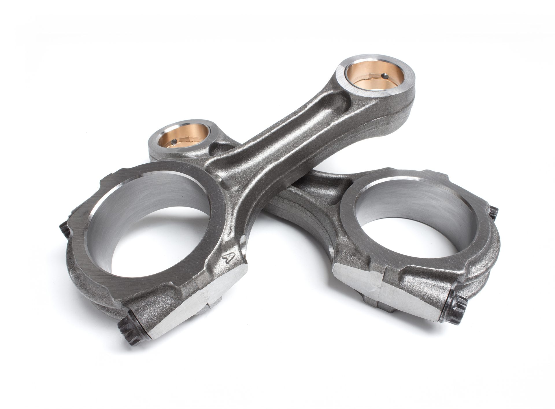
But first, why is this dimensional check important? Consider the connecting rod (conrod) that attaches the piston and crankshaft in an automotive engine. The center-to-center distance of the smaller bore to the larger bore plays a very important role in the overall performance of the engine, where even a very small deviation from the allowed tolerances can cause engine vibration or even engine breakdown under heavy loads. In aerospace, turbine housings need bolt holes spaced precisely to distribute loads evenly and maintain structural integrity. These examples highlight the importance of center-to-center accuracy in an assembly. In all of these, air gaging steps in as a fast, accurate, and reliable method of gaging.
So, how does air gaging handle something as specific as the center-to-center distance between bores? It’s all about clever tooling configuration. A standard setup of such an air-gaging solution is shown below.
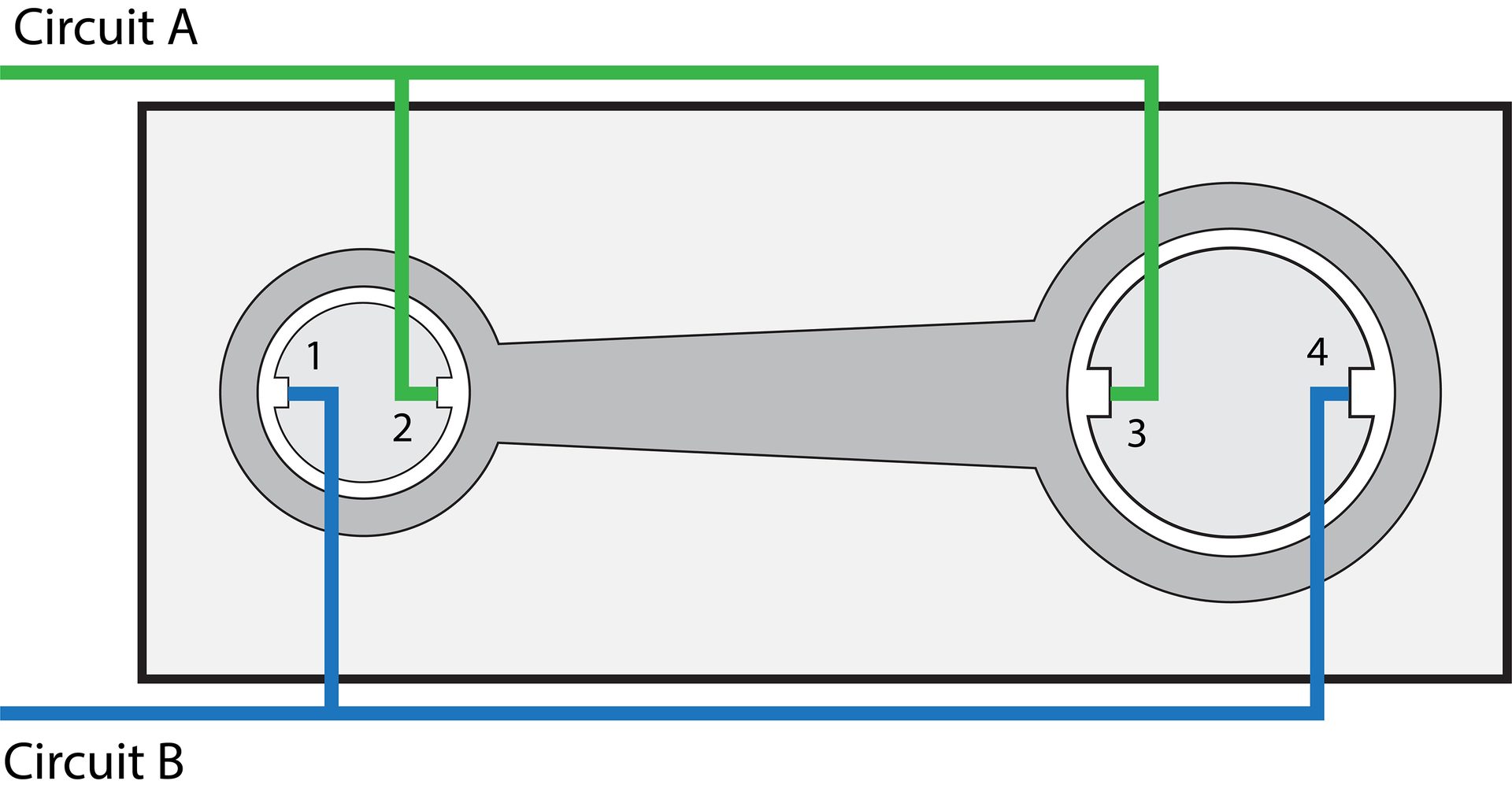
Figure 1: Center-to-center distance setup
Figure 1 shows a typical setup for checking the center-to-center distance of a part, for instance, a conrod. In this setup, jet 1 of the left plug is paired up with jet 4 of the right plug in circuit B, and jet 2 of the left plug is paired up with jet 3 of the right plug in circuit A. Note that in this setup, the plugs are fixed in place on a baseplate, and they cannot move. The distance between the centers of the air plugs is set to match the nominal distance according to the part’s design. It is also worth noting that there are other setups where one gage is fixed in place and the second one is mounted on a floating fixture to allow the gage to move slightly and align itself inside the bore, but this is not in the scope of this article.
How it works
The workings of this setup will be detailed using unitless numbers for distance and pressure to make it easy for the reader to follow. For this purpose, according to design, assume that the nominal part looks like Figure 2, where the smaller bore has a diameter of 10, the larger one has a diameter of 20, and the distance between the centers of these two bores is 50 units.
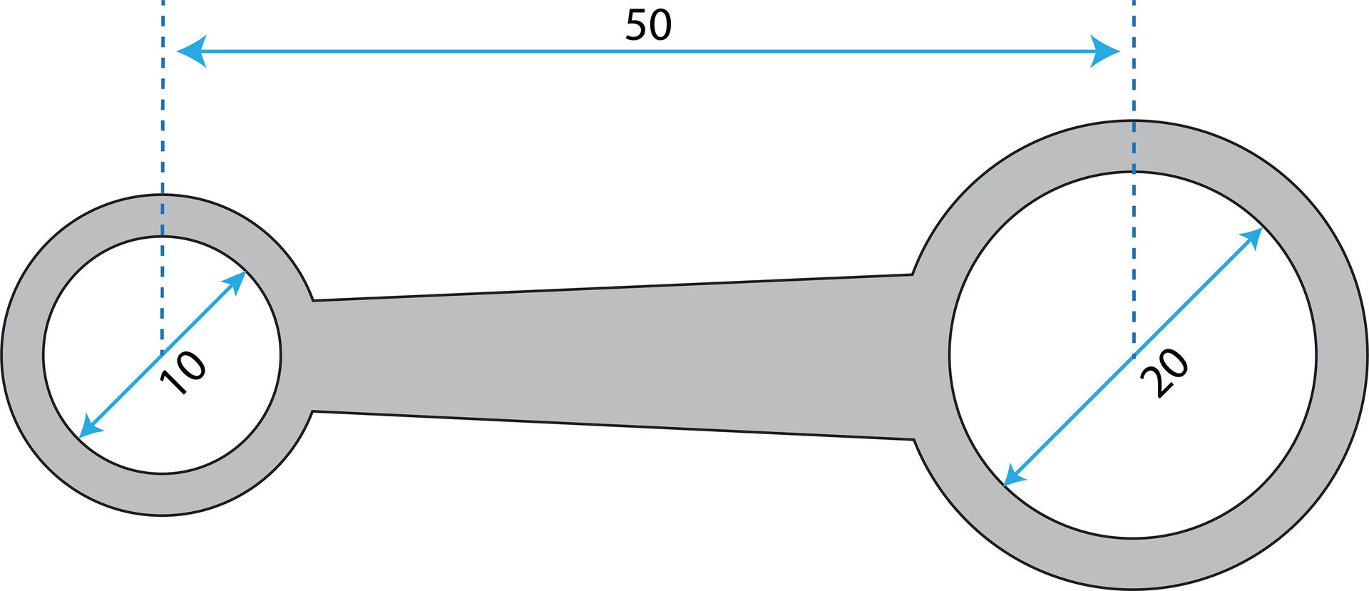
Figure 2 – an ideal part and its dimensions.
Let’s call this part the nominal part, which somehow magically was manufactured spot-on with no deviations from the designed dimensions. We will place this nominal part on the air gaging fixture and explain what the two air circuits and their air jets will experience.

Figure 3: The nominal part on the gaging fixture.
This nominal case is where the center-to-center distance of the left and right plugs (as well as the bores) is 50. The part is placed on the gage, and all jets have an equal clearance from the part, that is, the distance from the jet to the wall of the bore. An equal amount of air escapes from all four jets, and as a result, the back pressure in circuit A is equal to circuit B. This back pressure is assigned a unitless number such as 100, where 50 comes from one jet and the other 50 comes from the second jet. A back pressure of 100 for each circuit means the ideal situation, i.e., the center-to-center distance of the small and large bore is spot on according to design, and it is 50. Assume that every 10 units of change in back pressure correlates to 1 unit of change in distance.
Now, let’s go back to the real world, where manufactured parts are not perfect, and there are some deviations from the design caused by tool wear, machine error, etc. Consider a case where the distance between the centers of the two bores is now two units shorter than the nominal, and it is 48. We will explain what happens to the clearance spacing for each air jet, how this change in clearance affects the back pressure, and how this change in back pressure can be related to distance. Figure 4 depicts this situation. Note that the location of the air plugs did not change as they are fixed in place on the base plate.
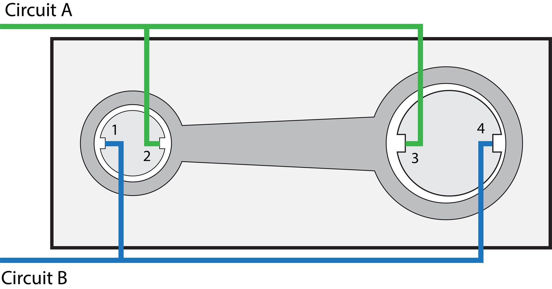
Figure 4: The case when the center-to-center distance is two units shorter than the design.
In this case, for simplicity, assume that it is the larger bore that is somehow shifted to the left of the nominal position by two units. Since the smaller bore didn’t move, jets 1 and 2 will see no change in airflow and back pressure compared to when the ideal part was on the gage. They both will sense a 50 back pressure.
Things are not so good with the other plug on the right and its jets. The clearance of jet 3 has now increased by two units, which means that air can now flow more easily, thus resulting in a reduction in back pressure since the gap has increased by two units. Assume that the back pressure drops by 20 units, and jet 3 is now sensing 30 instead of 50. Similarly, the clearance of jet 4 to the wall of the bore has now decreased by two units; air has a harder time escaping, and the back pressure that jet 4 senses increases. This jet now sees a back pressure of 70.
Analyze each circuit (and do not forget that these numbers only serve to show how the concept works and in real life, these 1-to-1 relationships do not exist):
Circuit A: sees 50 from jet 1 and 70 from jet 4, average of 60.
Circuit B: sees 50 from jet 2 and 30 from jet 3, average of 40.
Circuit A sees a 10-unit increase in its back pressure compared to the nominal situation, and circuit B sees a 10-unit decrease in the back pressure. This gaging system works based on the differential pressure method. The difference in back pressure between circuit A and circuit B is shown in equation 1:
Equation 1: The formula for the differential pressure method.
Circuit A – Circuit B = 60 – 40 = 20
Remember that we assumed that every 10 units of change in back pressure relates to 1 unit of distance, so in this case, 20 units of change in the total back pressure that the system detects means that there are two units of distance change. The distance between the bore centers is now 48 instead of the nominal 50. With this setup, a positive change in the total back pressure means that the center of the bores is closer together than the nominal case, and a negative change in back pressure means that the bores are now further apart than the nominal situation.
With these unitless numbers and assumptions, it is now easy to imagine the situation where the bores are farther apart than the nominal distance; one can easily use the logic explained above to work out the distance offset from the designed value.
It is worth noting that this setup and jet configuration assume that the bores are circular; this system is unable to detect any deviations of the bores from a circular form. It also does not check the diameter of the bores due to its unique jet configuration. One could modify this system by adding two more opposing jets in each plug and check the size as well. Air gaging is well known for its versatility.
Conclusion
Center-to-center spacing is not just a number, it’s the heartbeat of countless mechanical systems, from engines to turbines. An air-gaging solution such as the one discussed above— with its fixed and base-mounted plugs, distanced precisely to match the designed distance and differential pressure method—offers a practical answer to the challenge of checking this dimension.
By sensing back pressure shifts through jet clearances, averaging them in cross-paired circuits, and translating the differential back pressure into a precise deviation, it delivers speed, accuracy, and reliability. Whether ensuring a conrod keeps an engine running smoothly or a turbine withstands heavy loads, air gaging proves that sometimes the simplest ideas, like using air to measure distance, can solve challenging problems.