Measurement
Turning GD&T
From Grim, Depressing & Troublesome Into Something Grand, Delightful & Tantalizing
For the sake of industries around the world, it is time to make GD&T much easier to use, and much easier to use correctly.
By Bill Tandler
What is GD&T? GD&T (Geometric Dimensioning & Tolerancing) is a symbolic language for researching, refining and ultimately encoding the functions of each feature of a machine part in order to specify permissible limits of imperfection to guarantee assembly and operation. Without GD&T, design processes cannot be function based, tolerance stack up analysis is impossible, manufacturing is a guessing game based on tribal understandings, and coordinate metrology is impossible. In spite of these reasonably well known, very positive forces, GD&T is not widely used, is rarely taught at universities and if used, is frequently misused. Why? Because the main resources for its use, the ASME and ISO GD&T standards, have become exceedingly complex and confusing in recent years. This includes 1) confusing terminology, 2) confusing symbols, 3) non-functional concept definitions, 4) a huge lack of rules and 5), a lack of application process guidelines. For the sake of industries around the world, it is therefore time to make GD&T much easier to use, and to use properly. But how? We will start with examples proving the need for repairs, then present examples of possible repairs, and finally, present ideas for encouraging and enabling their implementation.
GD&T Confusion
Here, then, are a number of examples of confusing Y14.5 Standard terms and definitions, along with recommended improvements. Reviewing these entries will require patience and perseverance, but doing so will produce significant new clarity and hopefully a desire to begin pushing for a brand new standard - a simplified, clarified, “rulified” gift we so desperately need.
1.1 Terminology Revision – Material Condition Modifiers (S), (M) and (L):
Consider replacing the term: Material Condition Modifiers (S), (M) and (L) with the term “Tolerance Zone Size Modifiers”. These modifiers do not “modify the condition of the material of a feature”, but instead either fix [ (S) ] or increase [ (M) or (L) ] the size of the tolerance zone imposed on a feature’s symmetry component, as the feature departs from its virtual in-space (M) or virtual in-material (L) boundary. (S) requires the tolerance to be (S)tuck at its indicated value, (M) provides (M)ore tolerance as the feature departs from its virtual in-space boundary, and (L) provides (L)ots of tolerance as it departs from its virtual in-material boundary.
1.2 Symbology Extension – An Additional Tolerance Zone Size Modifier:
Consider extending the (S), (M) and (L) set with an “in-material” Regardless of Feature Size modifier (S-) to enable a currently missing capability, and changing the current (S) modifier to (S+) to clarify its impact, resulting in the new set (S+), (S-), (M) and (L).
1.3 Terminology Revision – Material Boundary Modifiers (S), (M) and (L):
Consider replacing the term: Material Boundary Modifier with the term “Tolerance Zone Mobility Modifier". These modifiers do not “modify the material boundaries of Datum Features”, but instead either impose (S)tability, or permit residual (M)obility in space, or residual (L)ability (as in “labile” = looseness) in material, of Datum Feature Simulators relative to their mating Datum Features. Example: The modifier (M) permits taking advantage of residual play between mating Datum Features during assembly.
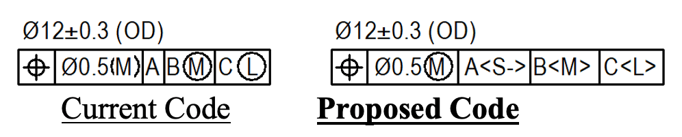
1.4 Symbology Revisions & Extensions - Tolerance Zone Mobility Modifiers:
In order to eliminate user confusion regarding the difference between the impacts of Tolerance Zone Size and Tolerance Zone Mobility modifiers, consider making the latter also look different, namely switching from (S), (M) and (L) to , and , and, in order to impose in-material as well as in-space stability requirements, including the modifier .
1.5 Definition - Datum Feature:
Current Definition Y14.5 2018: (§3.17 p.6) a feature that is identified with either a datum feature symbol or a datum target symbol.
Recommended Definition: A specially labeled, imperfect physical surface of a real part which serves to constrain rotational and translational degrees of freedom between mating parts during assembly and, when listed in a Feature Control Frame, contributes to defining a Datum Reference Frame.
1.6 Definition - Datum Feature Simulator:
Y14.5 2018 Definition: (§3.18 p.6): The physical boundary used to establish a simulated datum from a specified datum feature.
Recommended Definition: Datum Feature Simulators are perfect imaginary (in the world of CAD), or almost perfect real (in the world of manufacturing and gaging), inverse Datum Features, which represent the mating Datum Features of a part, and
- from which we extract Datums,
- in which we first establish Datum Reference Frames,
- and with which we transfer Datum Reference Frames to actual parts, by mating them with their associated Datum Features.
Because DRFs (Datum Reference Frames) are absolutely stable inside their simulator sets, simulators which are free to residually rock, roll or trantslate relative to their mating Datum features produce residually mobile DRFs and associated tolerance zones, which represent play between mating parts during assembly.
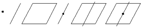
1.7 Definition - Datum:
Y14.5 2018 Definition (§3.14 p.5) a theoretically exact point, axis, line, plane, or combination thereof derived from the true geometric counterpart.
Recommended Definition: A Datum is the minimum, mutually embedded set of a single, perfect imaginary reference point and/or line and/or plane extracted from a Datum Feature Simulator, which together, fully characterize its orientation and location. Purpose: Datums serve to constrain “starter” coordinate systems and turn them into Datum Reference Frames. Here are images of all six possible Datums;
1.8 Definition - Datum Reference Frame:
Y14.5 2018 Definition: (§3.19 p.6) Three mutually perpendicular datum planes and three mutually perpendicular axes at the intersections of those planes. Commentary: in other words, a Cartesian coordinate system!!! Why not call it that?
Recommended Definition: A Datum Reference Frame is a Cartesian coordinate system, which is partially or fully constrained by a set of Datums extracted from a set of Datum Feature Simulators, defined by a set of Datum Features listed in a Feature Control Frame. Purpose: Datum Reference Frames serve, with the help of Basic dimensions, to orient and locate tolerance zones in the part under consideration, and relate them to the tolerance zones in the mating part.
Example: Consider a part with a primary cylindrical Datum Feature A which constrains pitch, yaw and two degrees of translational freedom, and a secondary Datum Feature B, in the form of a countersink whose axis is perpendicular to A, which, when engaged by a mating sphere, constrains roll and the last degree of translational freedom. Their associated Datums are a line in the case of A and an offset point in the case of B. The two Datums themselves do not represent a Datum Reference Frame, but actually serve only to constrain a three axis “starter” coordinate system and turn it into the applicable Datum Reference Frame.
1.9 Feature Control Frame Decoding:
Y14.5 2018: Note: No Feature Control Frame decoding processes are found in the Standard.
The Feature Control Frame Decoding Process: In order to be fully functional, the encoded instructions in a Feature Control Frame must be uniquely decodable and certainly not open to “interpretation.” Here is an example applied to a shaft using the newly recommended Tolerance Zone Mobility modifiers , , and :
The decoding process: “Position requires the bounded axis of the shaft to lie within a cylindrical tolerance zone of diameter 0.5mm at MMC, expanding by as much as 0.6 mm as the shaft departs from Maximum toward Least Material Condition, which is oriented and located by Basic dimensions relative to a Datum Reference Frame established using Datum Feature A simulated
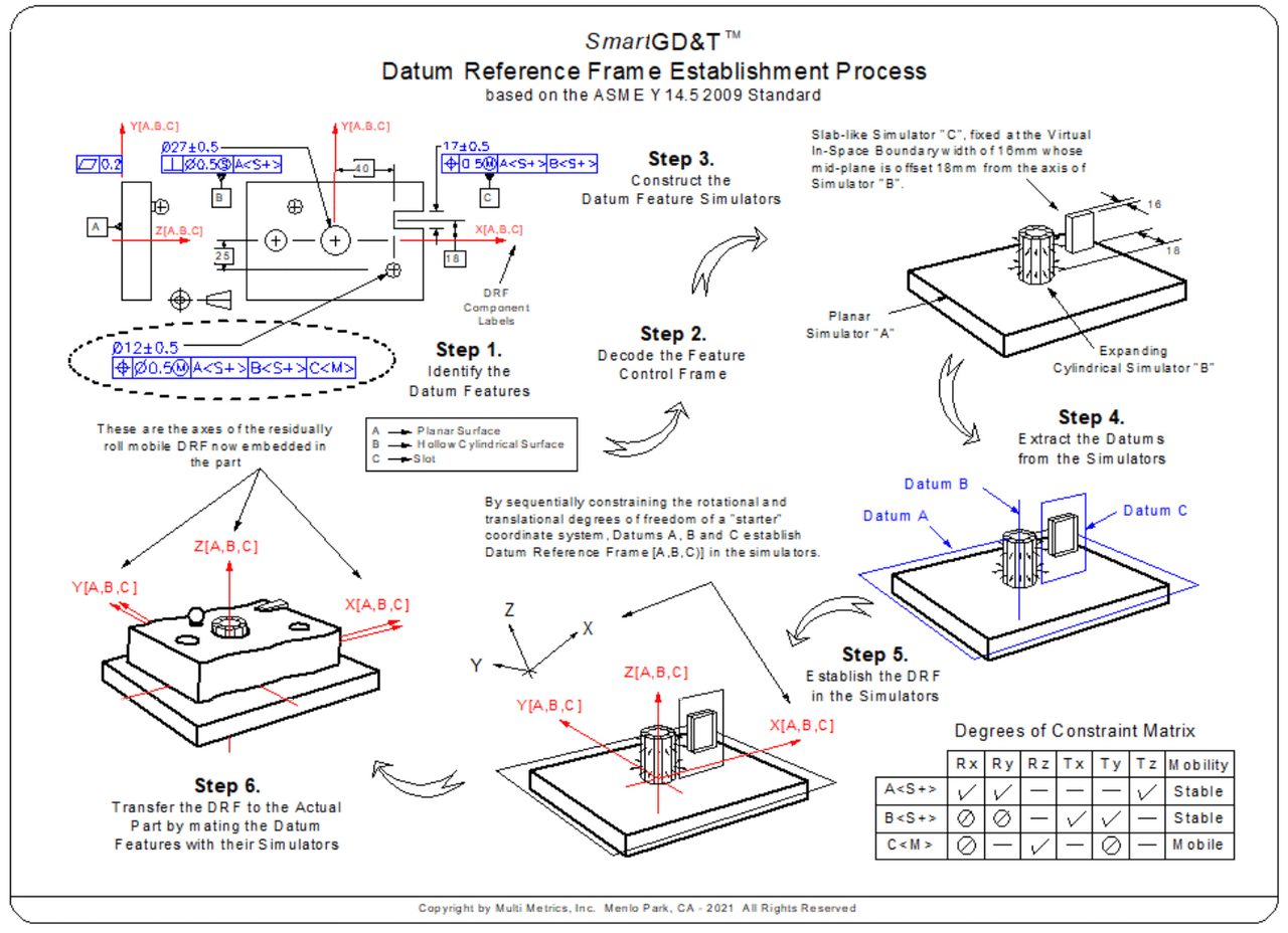
1.10 Datum Reference Frame Establishment Processes & Rules:
Y14.5 2018 Process Definition: Datum Reference Frame concepts are dealt with in the Standard’s §7, including text: pp.70-84, and illustrations pp. 85-147, but contain no definition of the Datum Reference Frame establishment process or associated rules.
Recommended Datum Reference Frame Establishment Process Steps & Rules: Datum Reference Frames are established using the following steps and rules:
Process Steps:
- Step 1. Identify the Datum Features.
- Step 2. Decode the Feature Control Frame. |_xx | Ø yy(M)| etc.
- Step 3. Construct the Datum Feature Simulators.
- Step 4. Extract the Datums from their Simulators.
- Step 5. Use the Datums to Constrain a Starter Coordinate System in the Simulators.
- Step 6. Transfer the Datum Reference Frame to the actual part by mating its Datum Features with their Simulators.
Process Rules:
- Rule of Datum Feature Precedence (Y14.5M 2009 §4.10 p.58): Datum Features shall be used in the order in which they appear in the defining Feature Control Frame, reading from left to right.
- Rule of Degrees of Constraint Precedence (SmartGD&T): Each Datum Feature shall first attempt to constrain pitch and yaw, then roll and only then, any remaining degrees of translational freedom.
- Rule of Non-Override (SmartGD&T): No Datum Feature may override degrees of freedom partially or wholly constrained by higher precedence Datum Features.
- The Can-May-Must Rule (SmartGD&T): If a Datum Feature can (is able to) and may (is permitted to) constrain a degree of freedom, it must.
1.11 Example of the Datum Reference Frame Establishment Process & Rules:
Ideas for Enabling Creation of a New GD&T Standard
It is hoped that the above entries have enabled readers to discover the trouble we are in and the burning need for a new standard based on simplicity, clarity, processes and rules, in order to enable enjoyable and functional use of this magnificent tool. If so, the next step must be to make it happen. But how?
The most effective – actually the only - way to clean up something so complex, in which every piece of the pie depends on every other piece, is to start over. The common approach has always been to try to fix the existing Standard, but, as demonstrated by the current Y14.5 2018 version, this did not work, nor will it ever work in the case of a so many faceted, complex topic. The old always gets in the way of the new. Therefore, the only way is to start over, as was the case with the British system of weights and measures when it was replaced by the French Metric System. And so, it is time, it would seem, to encourage the Y14.5 Committee to start over, namely to form a “GD&T Development Group” consisting of proven experts who are totally focused on the project and absolutely dedicated to getting things right - not to proving they are right - and who also feel that the sooner proven wrong, the better. And, in addition to an expert “Development Group,” the Committee must also be encouraged to form an expert “Review Group,” and hopefully pay all the members for their time, and maybe even pay them royalties to encourage aggressive, dedicated performance.
If readers are inclined to proceed, please review the source document (see the link below) containing the entries used in this article plus many more, and then forward it with your comments to Fred Constantino, the secretary of the ASME Y14.5 Standard Committee (ConstantinoF@asme.org ), in order to encourage them to investigate and possibly address these concerns and ideas. They have lots of good people who will surely be interested. And perhaps share a possible financing idea as well: namely recommend that corporations around the world who recognize what they are missing, participate in financing the project, maybe in exchange for receiving free access to the new standard for an agreed upon number of years.
Thank you for taking the time to read the article and, if you agree with its content and objectives, special thanks on behalf of the whole world for gently encouraging our standard committee to consider these and the many additional recommendations to be found in the source document.
Note: To download the source document “Proposal for a Clarified, Simplified, Rules & Processes Based, New ASME Y14.5 Standard” go to: https://www.dropbox.com/s/10flnteb1sme1gg/- Proposal for a Clarified-Simplified-Enhanced-and Rule Based Y14.5 Standard V8 2021-11-06.docx?dl=0
Opening Video Source: gorodenkoff/Creatas Video+ / Getty Images Plus via Getty Images.
Remaining Images Source: Multi Metrics
Bill Tandler, Multi Metrics Inc. For more information, please email bill@multimetrics.com.
February 2022 | Volume 61 | Number 2