Machine Vision 101
Machine Vision 101
Vision & Sensors
V&S
When considering illumination, the object or field to be imaged is really what matters. By Florian Gollier
Machine Vision Lighting
As the field of machine vision grows, it becomes increasingly important to understand what makes a machine vision system work well. The point of a machine vision system is to provide an image that makes it easy for a software package to do what needs to be done with said image. As such, it is important to have all of the parts of the machine vision system work in congruence. One of the most notable, and yet most often forgotten, parts of an imaging system is the lighting, or illumination. The camera and lens play an important part in the imaging system but these are more akin to the foundations of a building. In order to create a building worth mentioning, one needs to build on top of the foundations, this being illumination in an imaging system. Not unlike in construction, illumination is often what takes the most time when considering an imaging application. This is because lighting is so application specific. Specific camera and lens combinations can sometimes be used for different applications but very rarely does illumination geometry not vary between different applications.
When considering illumination, the object or field to be imaged is really what matters. There are so many different considerations but the important ones are as follows: transmissivity and surface texture. Transmissivity can be broken down into whether an object transmits light, absorbs light, or reflects light. Reflectivity can then can be broken down according to surface texture into specular reflections, or more mirror-like reflections, and diffuse reflection, or reflection more similar to how a piece of paper reflects. Knowing these properties makes it very simple to choose an illumination system that will maximize the efficiency of the imaging system.
Types of Illumination
Oftentimes, lighting is referred to as “illumination geometry” as the placement of the illumination in the system plays a key role in how it works with the object being imaged as well as the imaging system, this being the lens and camera. There are three major geometries: lighting from the back, lighting from the front, and lighting from the side. Each of these present their own benefits and difficulties.
Lighting from the Back
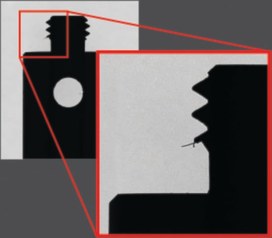
Lighting an object from behind is a great idea both when the object is transparent as well as when the object is opaque, albeit for different applications. Opaque objects with a backlight can be measured with incredibly accuracy. The light from the backlight hits the opaque object and does not reach the lens, which will show an obscuration where the object is, and a bright field on the outside of the object (Figure 1).
This contrast between the object and the background allows for accurate measurement of dimensions.
For transparent objects, a backlight can allow for sorting of colors. Transmissive objects will transmit different wavelengths depending on their color, which allows for color detection in transparent colored objects.
Figure 2. Diffuse backlight hitting an opaque object
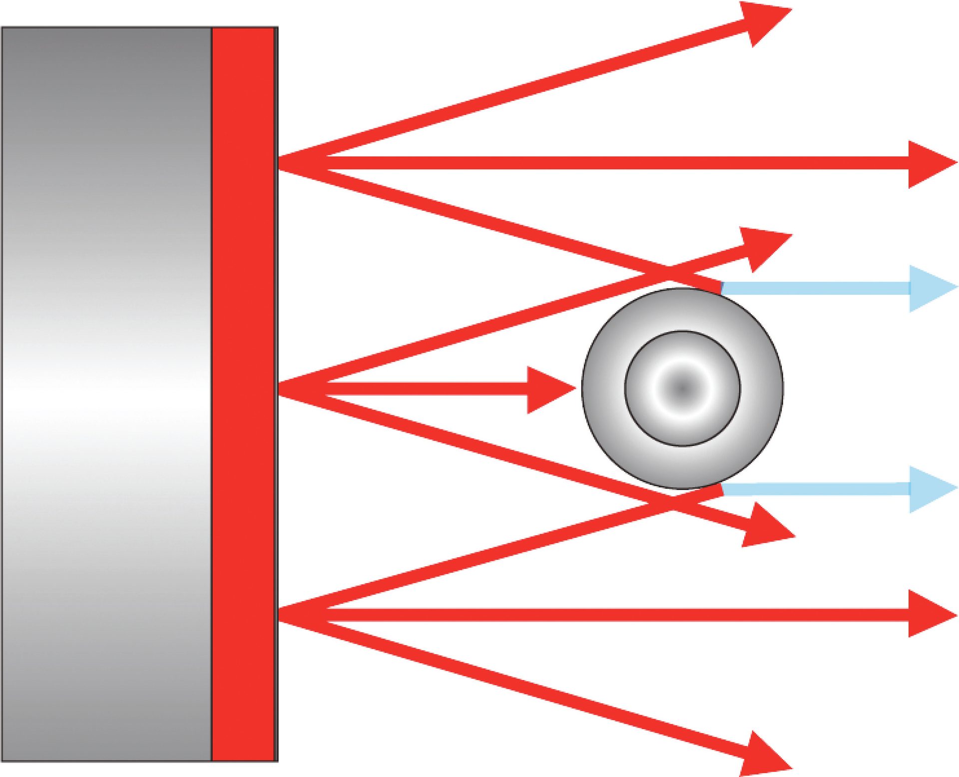
Figure 1. Backlight illumination with a dark silhouette and bright field outside of the silhouette
It is important to note that there are many different types of backlights. Backlights can be diffuse, collimated, or telecentric. A diffuse backlight sends out diffuse light through the use of a diffuser. This will create more even lighting but will create difficulties when needing sharp edge finding, as the rays coming from sharp angles will bounce off the edge resulting in a loss of contrast on the edges. However, for targets and test patterns, this technique tends to be ideal as it provides a very even illumination with which to assess imaging system performance very accurately (Figure 2).
This contrast loss can be eliminated when specifically using telecentric lenses with telecentric backlighting. This backlighting revolves around similar concepts as telecentric lenses as the chief rays exiting the illuminator will be parallel to the optical axis. Telecentricity revolves around this idea of parallel chief rays to the optical axis. This removes parallax errors and creates lenses with a specific magnification that makes measurements very accurate and repeatable. When coupled with the appropriate telecentric lens, telecentric illuminators allow for the majority of the light to reach the sensor when aligned properly. This also allows for high contrast edges as any parallel rays hitting an edge will not reach the lens resulting in a purely dark obscuration whereas any ray not hitting an object on its way to the lens will travel through to the sensor (Figure 3). This makes telecentric illumination ideal for dimension measurement for opaque objects.
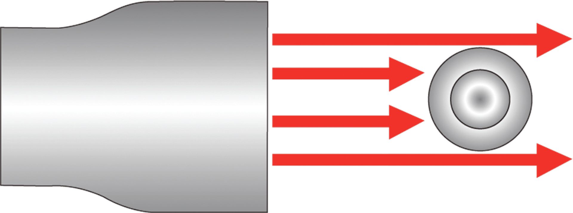
Figure 3. Telecentric illumination with parallel rays getting obscured by an opaque object
These illuminators, however, do tend to be fairly expensive, need to be aligned accurately, and tend to take up a lot of room.
There does exist a balance between a diffuse and telecentric backlight illuminator, which comes in the form of a collimated backlight. These tend to have shallower chief ray angles than diffuse lights but will not have the parallel chief rays of the telecentric illuminator. Depending on the illuminator, this angle varies but tends to be around 10 degrees in divergence. These illuminators are much cheaper and compact than telecentric illuminators, work for fixed focal length lenses, and are much easier to set up.
Though backlighting works well for a lot of applications, it should be noted that for opaque objects, a backlight will not illuminate the surface facing the imaging system (Figure 4). For transparent objects, one is usually looking for defects or obscurations but the surface is still never really in clear focus.
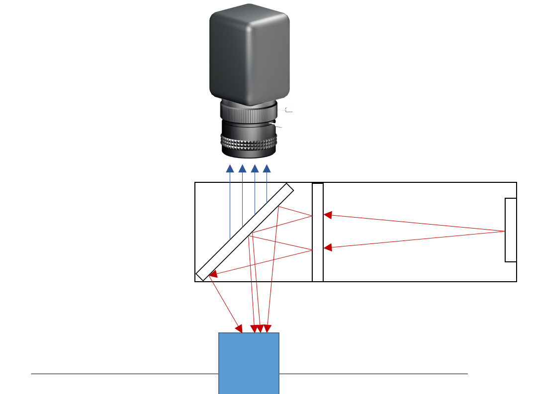
Figure 5. Setup for diffuse axial illumination
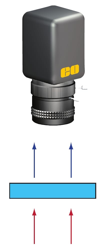
Figure 4. Backlight through transparent object
Lighting from the Front
To view the surface of an object, coaxial lights are often used. These illuminators tend to coincide with the view of the imaging system. However, because the imaging system still needs to see the object, for the light to coincide with the optical axis, it needs to be out of the way of the field of view of the camera. This is done by using a ring light, or a light with a hole in the middle, or with beamsplitters.
A ring light is fairly simple as it is, as its name suggests, a ring of lights with a hole in the middle for the lens to look through. These are great for uniform, on-axis illumination but will only work for certain working distances and will create a circular glare on reflective surfaces.
To remove this circular glare pattern on reflective surfaces, on-axis diffuse light can be very effective. These lights use a beamsplitter to redirect a diffuse light source into the optical path (Figure 5).
These systems provide very even illumination with little glare and shadowing, which makes them great for inspection of shiny objects. They are, however, fairly large due to the presence of the beamsplitter and tend to be difficult to mount. The throughput tends to also be low as the light coming into the lens has travelled through a beamsplitter twice, a process which each time reduces the light in half.
The last common coaxial light source is in-line illumination. This illumination geometry also utilizes a beamsplitter but does so inside of the lens. The beamsplitter is introduced into the path of the optics and the light is folded into the optical path inside of the lens (Figure 6).
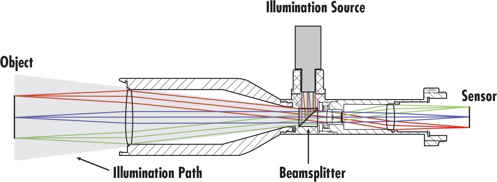
Figure 6. In-line illumination
When looking at in-line illumination, it is important to understand the concept of specular versus diffuse reflection. Specular reflection is similar to the way a mirror reflects. A single ray will reflect into another ray with very similar intensity at an angle which is proportionate to the angle it came into the mirror.
Diffuse reflection breaks up the incoming ray into a multitude of smaller intensity, different angled rays. This is similar to the way a piece of paper reflects.
In-line illumination works specifically great for specular or semi-specular surfaces as the incoming rays are parallel to the optical axis and a specular surface will simply reflect these right back into the lens. This provides great detail in the image. In-line illumination is also great for saving space, as the light is folded right into the lens’ path. These systems, however, do suffer from some stray light if not correctly designed and also reduce light throughput due to the use of a beamsplitter.
Lighting from the Side
The last lighting geometry is darkfield illumination, in which light shines through the sides of an object and reflects into the lens (Figure 7).
In this technique, the object is essentially dark with defects or features appearing brighter as light is reflected off these features into the lens. Darkfield illumination is ideal for defect detection on the surface or in the interior of transparent objects. A lot of darkfield applications revolve around glass and plastic defect detection. Darkfield illumination does not work, however, for opaque objects and tends to have poor edge contrast when trying to find edges.
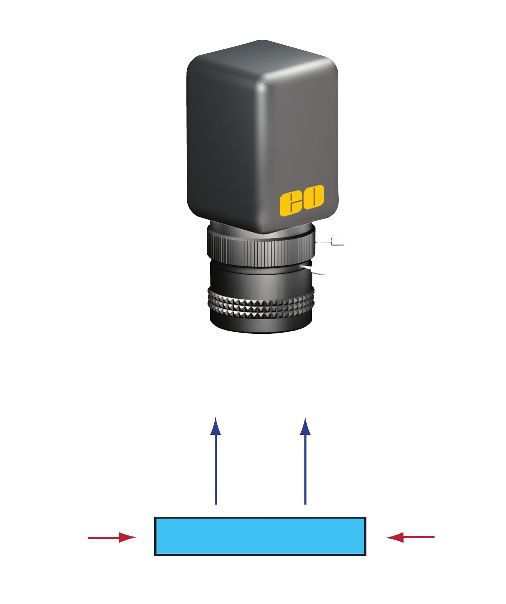
Figure 7. Darkfield illumination
It is clear from the above information that no illumination method or geometry can satisfy all applications and picking the correct one is key in producing the most optimal image for a machine vision system. Speak to your optics and illumination suppliers to ensure that all components of your machine vision system complement each other and allow you to meet your application requirements.
Opening Video Source: grdenis / Creatas Video+ / Getty Images Plus via Getty Images.
Remaining Images Source: Edmund Optics
Florian Gollier is an optical engineer at Edmund Optics. For more information, email fgollier@edmundoptics.com.
December 2022 | Volume 61 | Number 12