xxxxxx xx
xxxxxxxxxx
Fatigue Testing
NDT
NDT
A Time-Tested Method for Modern Material Evaluation. By Richard J. Gedney
Rotating Beam Fatigue Testing
Material fatigue is one of the most critical concerns in modern engineering, and some studies estimate that over 90% of material failures in service result from fatigue stress rather than simple mechanical overloading. As industries continue to push the boundaries of material strength and performance, the need for efficient and cost-effective fatigue testing methods has become increasingly important. Rotating beam fatigue testing, a methodology tracing back to the mid-1800s, offers a compelling solution for researchers and quality professionals seeking to evaluate material endurance limits while managing both time and budget constraints.
Origins of Rotating Beam Fatigue Testing
The concept of rotating beam fatigue testing emerged from practical necessity during the industrial revolution, after several catastrophic failures of railroad components led corporations to investigate their materials’ performance systematically. During the 1850s, German railroad engineer August Wöhler developed the first rotating beam fatigue testing apparatus to investigate axle brake failures and test railroad car axles. His work established fundamental principles that remain relevant today, including the relationship between stress amplitude and fatigue life, and the concept of an endurance limit, and intrinsic point of any material under which fracture under cyclic loading will not occur.

Wöhler’s approach in the mid-1800s enabled him to relate rotating beam testing results to actual locomotive axle stresses, culminating in an 1870 report that contained several conclusions fundamental to modern fatigue analysis. The intervening years have brought many innovations in fatigue testing; however, the core principle remains unchanged: to determine the fatigue characteristics of a material, one must subject it to controlled cyclic stresses.
Today, rotating beam fatigue testing still serves as a valuable tool for this purpose. Researchers around the world are using the rotating beam fatigue approach to characterize the fatigue behavior of novel metal alloys, due to the potential for fast, high-cycle testing. Quality professionals in the aerospace and automotive industries rely heavily on rotating beam fatigue testing data to manage risk and ensure safe, efficient, and long-lasting product designs. We have seen growing interest in this solution from medical device and implant companies as well. As material testing requirements have grown more sophisticated, rotating beam fatigue testing has maintained its relevance by offering unique advantages in testing frequency and cost-effectiveness compared to traditional methods.
What’s In a Rotating Beam Fatigue Testing Machine?
In essence, rotating beam fatigue testing machines rotate a round test sample at very high speeds and apply a bending moment to it as it rotates. This setup creates fully reversed stress cycles in the material as it turns, often at rates up to 100 Hz, resulting in a more efficient means of applying cyclic stress to determine endurance limit (relative to uniaxial fatigue tests).
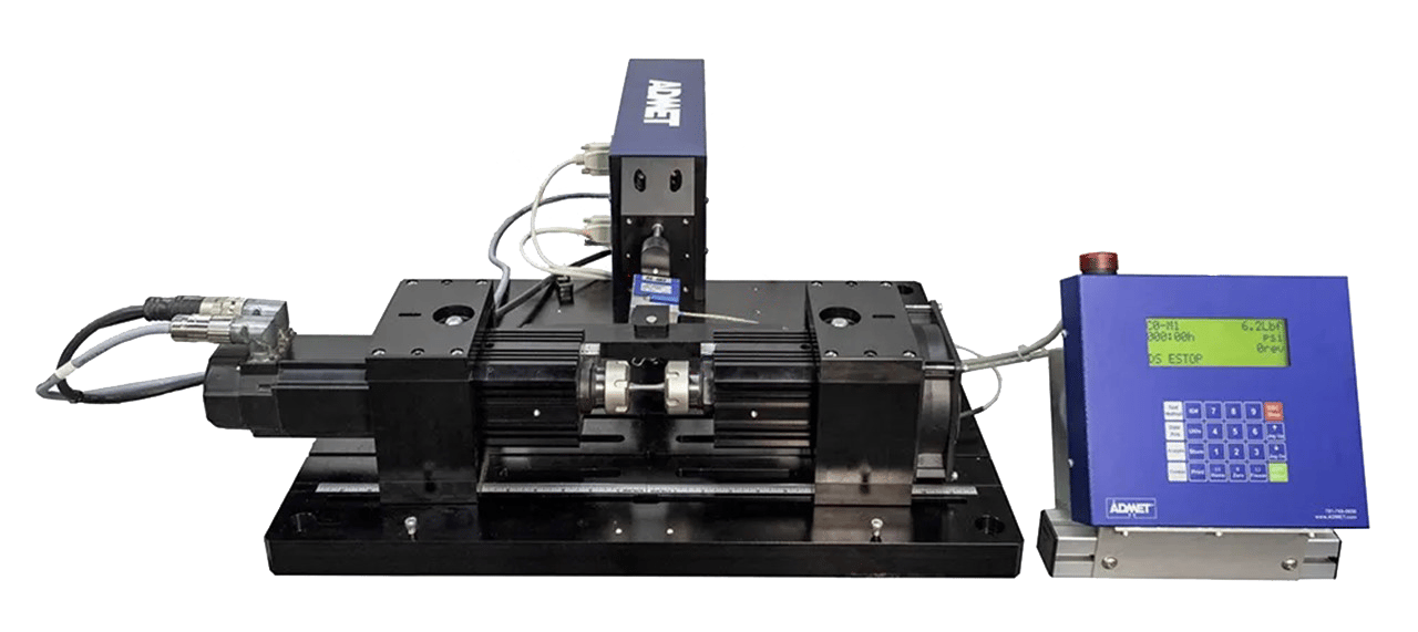
Shown in Figure 1, a typical rotating beam fatigue testing system includes the following components:
- A central motor and spindle held by precision bearings
- A pair of collets to securely hold the test sample
- A loading mechanism, electromechanical or deadweight-driven, that applies bending moment
- A load cell to measure and record the bending moment
- A digital controller to control test parameters and record all data
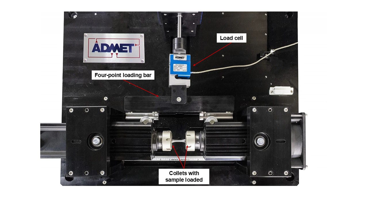
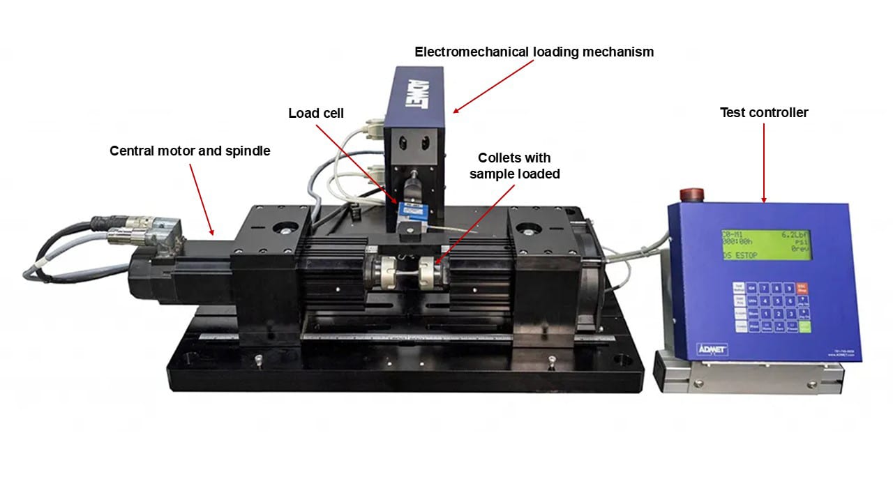
Figure 1. A dual pivot four-point loading rotating beam fatigue testing system with a servo controlled bending moment actuator. (Top and Front View)
Most modern machines allow users to specify rotation speeds from 600 to 6,000 RPM, which is useful for testing different materials and for studies that compare results at different speeds. Rotating beam systems can generally produce bending moments up to 50Nm (445 inch-pounds) and conduct fully reversing fatigue tests at up to 100 Hz cyclic frequency. Four-point- and cantilever-loading configurations are most common, and four-point loading is considered superior to single point cantilever systems because they produce a constant bending moment along the entire length of the specimen. Rotating beam fatigue testing systems are commonly fit with a furnace to characterize fatigue properties across a range of temperatures.
Principle of Operation
Sample Geometries
Most rotating beam fatigue testing is governed by ISO 1143 - Metallic materials — Rotating bar bending fatigue testing, which standardizes all test parameters and procedures for testing. All test samples must have a circular cross section, and have parallel, tapered, or hourglass geometries depending on how the bending moment is applied. The standard allows for a wide range of sample diameters and provides guidance on the fillet radius between the sample and shank diameters. Shank length is typically governed by the type of chuck or collet that is used to secure the test. A rotating beam fatigue testing system with four point loading requires a parallel specimen sample geometry as shown in Figure 2. Common sample diameters range from 2mm to 12 mm, however, larger sample diameters are possible.
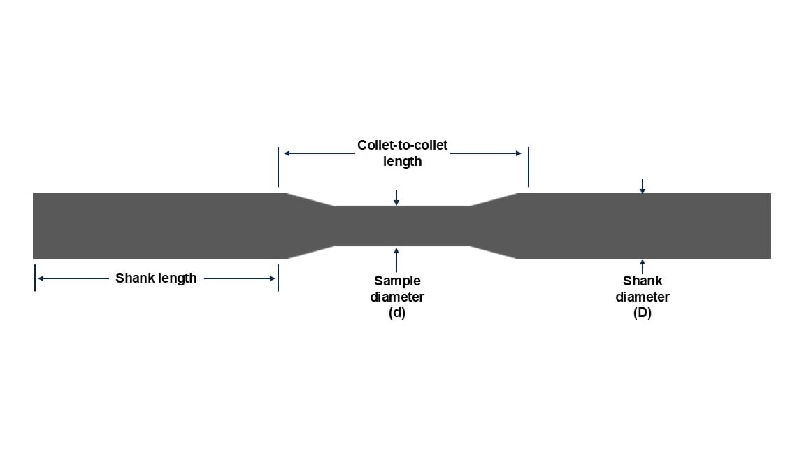
Figure 2. Sample Dimensions for Rotating Beam Fatigue Testing.
Loading and Stress
In the direct load four-point bending configuration shown in Figure 3, each spindle pivots about a point and the driven spindle is fixed whereas the pivot for the passive spindle rides on a linear bearing parallel to the axis of rotation. The linear bearing prevents axial forces as the specimen is flexed. A Force, F/2, is applied to each spindle a distance, L, from the pivot point thereby inducing only a pure bending moment to the specimen. When the specimen is rotated one half revolution, the stresses in the fibers originally below the neutral axis are reversed from tension to compression and vice versa. Upon completing the revolution, the stresses are again reversed so that during one revolution the test specimen passes through a complete cycle of tension and compression stresses.
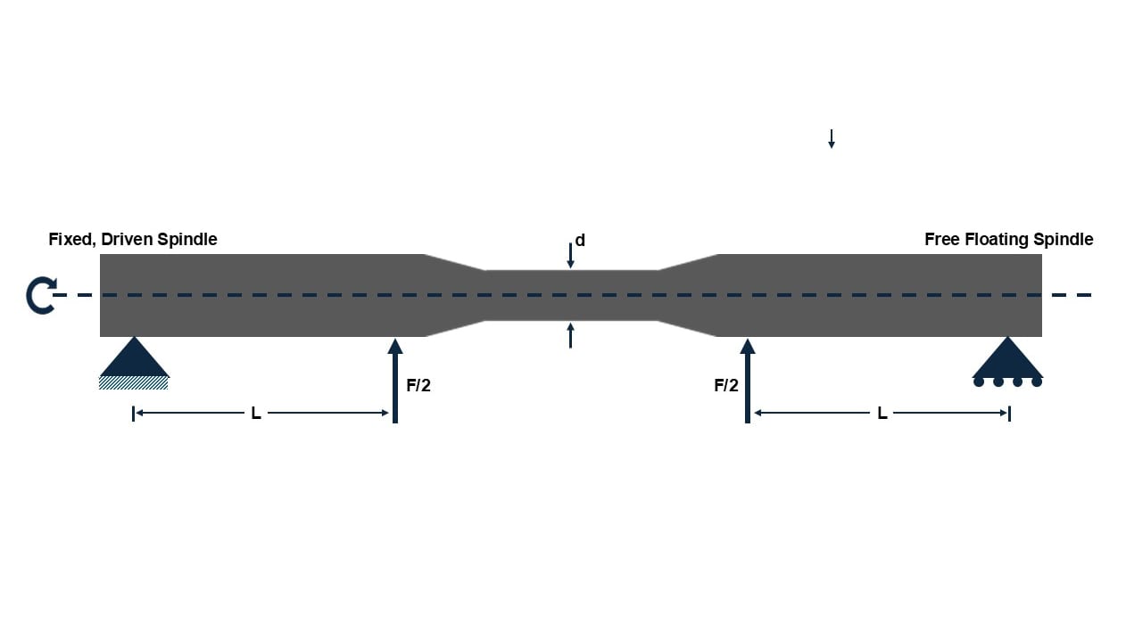
Figure 3. Loading Pattern for Rotating Beam Fatigue Testing.
The bending stress formula for the direct load four-point bending moment mode is shown below. For other loading conditions, it is recommended to consult ISO 1143, Table 2.
Bending Stress, S = 16 × F × L/(π × d3)
Where,
S = applied bending stress in pascals.
F = total applied force in newtons (Note: The ISO 1143 specification defines, F, as the applied force to each spindle).
d = sample diameter in meters
L = force arm length (0.1m for eXpert 9300)
To give a feel for the range of bending stresses that a rotating beam fatigue testing machine can apply, a 20mm and 5mm diameter sample subjected to a 50Nm bending moment (at each spindle) generates a bending stress of 64MPa (9.2ksi) and 4,074MPa (591ksi), respectively.
Fatigue Testing Theory
A key finding of Wöhler’s research in the mid-1800s was that there exists a cyclic stress amplitude below which a material can endure an “infinite” number of loading cycles without failing. Today, this stress level is known as the endurance limit. It is affected by material composition, microstructure, surface finish, temperature, and presence of stress concentrations. Endurance limits are typically determined through fatigue testing, where specimens are subjected to cyclic loading at various stress levels until failure or until a very high number of cycles (often 10 million or more) are reached without failure.
Building on this concept, Wöhler also produced the S-N curve (often referred to as the Wöhler curve), which reflects how many fatigue cycles a material can endure before failing at a specific stress amplitude. In practice, these curves are incredibly useful as they provide critical data for predicting how long a material or component will last under repeated or cyclic loading. Engineers commonly use S-N curves to design for safety and durability, support material selection, predict service life, and support industry and quality standards.
The Case for Rotating Beam Fatigue Testing
Rotating beam fatigue testing remains a go-to method for material characterization, offering unique benefits despite the rise of advanced testing systems. Its biggest advantage is speed: operating at up to 100 Hz compared to axial fatigue systems’ 10-20 Hz, it can complete million-cycle tests in under three hours, while axial testers might take a day or more. This efficiency, nearly 10x the axial option, delivers immense value for quality control and research teams. Cost is another win. Rotating beam testers are far more affordable, often costing a fifth of high-end axial fatigue systems, which can run into hundreds of thousands. They also require less maintenance, making them a budget-friendly choice for businesses adding fatigue testing capabilities.
There is no doubt that axial fatigue testing is still widely used in material testing for its flexibility in gripping, stress fields, and fatigue profiles, and its design which closely resembles other static testing machines. Nevertheless, anyone who has waited weeks to complete a test campaign or spent hundreds of thousands of dollars on a basic axial fatigue tester will recognize that faster testing system on a lighter budget can be a significant value driver for your business.
Conclusion
In conclusion, rotating beam fatigue testing is a proven, cost-effective method for material characterization, valued in modern labs for its high testing speeds and compatibility with axial fatigue methods. Originating from Wöhler’s 1850s research, it has evolved into advanced systems with precise controls, serving industries like aerospace and automotive by balancing thorough testing with efficiency.
As a complement to axial methods, it excels in rapid material screening and affordable data generation, maintaining relevance as industries innovate. Maximizing its value requires understanding its strengths and limits for material characterization and adhering to strict specimen standards. When applied well, this reliable method delivers critical fatigue insights with unmatched efficiency.