The World of
Indicators
Quality 101

As they have advanced over the years, the initial concept of the indicator still holds true: a need to measure small measurements and angles.
By Tim Cucchi
As they have advanced over the years, the initial concept of the indicator still holds true: a need to measure small measurements and angles.
By Tim Cucchi
Referred to as “an improvement in gages,” indicators were introduced in the late 19th century with the first patent dated May 15, 1883. John Logan, a watchmaker from Waltham, MA, saw a need for a precision instrument to measure small distances and angles with an uncomplicated value reading, and so he invented the indicator. One would imagine after some 130-plus years, indicators have changed. Indeed, indicators have evolved and many different types have been introduced such that there now exists a whole world of indicators.
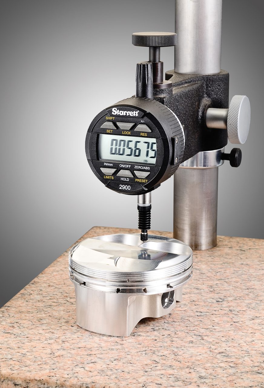
The dial type drop indicator was the first introduction of this precision instrument. Measurement with this type of indicator is obtained by the movement of a spindle multiplied with the reading of the dial in association with the needle. From this known point, one will be satisfied or adjust the manufacturing process to achieve the desired measurement. Usually held by the stem in a fixture, the indicator enables easy measuring to determine runout, height, flatness, and/or distance. Whether used in machining, setup, or for quality control, a drop indicator has many application uses. In 1945, the National Institute of Standards and Technology (NIST) set forth the American Gage Design (AGD) identifying standard classifications for the outer diameter of the indicator to facilitate an easy choice based on space in a specific application.
Specifically designed with shockless hardened stainless steel gear train and manufactured to fine watchmaking standards with jeweled bearings, the dial indicator has precisely finished gears, pinions and other working parts that make possible measurements from one-thousandth to 50 millionths of an inch, depending on accuracy requirements. Any gear unit and any case assembly can be combined to give a complete dial indicator of the style desired. Dial faces are color coded to avoid errors: white dial for English measurement and yellow face for metric.
The contact point is attached to a spindle or rack with movement transmitted to a pinion and then through a train of gears to a hand which sweeps the dial of the indicator. A small movement of the contact is thus greatly magnified and read directly from the dial in thousandths or as close as 50 millionths of an inch. Long-range indicators have direct reading count hands and a double dial. Dials can have balanced or continuous graduations.
When a dial indicator is subject to sudden blows or shock, a nonshock mechanism can be substituted for the regular mechanism. Impact and shock are completely absorbed and isolated from the gear movement. Any regular dial indicator can also be converted into a nonshock type by replacing the regular contact points with a shock absorbing anvil unit. The regular contact point may be replaced with contacts of almost any shape or length to suit the work. These include contact points of extra length, special form, tapered, and a roller contact for use on moving material.
The dial indicator is one of the most widely used tools today in layout, inspection and QC, and there are a wide variety of application variations including the dial caliper. An exceptionally versatile and easy to read instrument, four-way stainless steel dial calipers have knife edge contacts for inside and outside measurements, and a rod connected to its slide for obtaining depth dimensions. The rod contact is cut out to provide a nib for gaging small grooves and recesses. A dial comparator is another application example that is used for inspecting duplicate parts and various materials, either in bench inspection or on the production line.
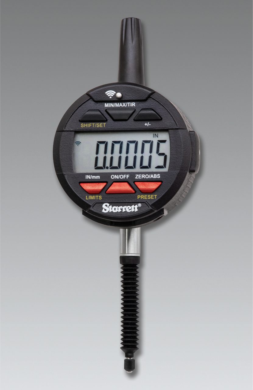
Wireless indicators are equipped to send data with a push of a button and feature IP67 protection against coolant, dirt, chips, water and dust found in harsh environments.
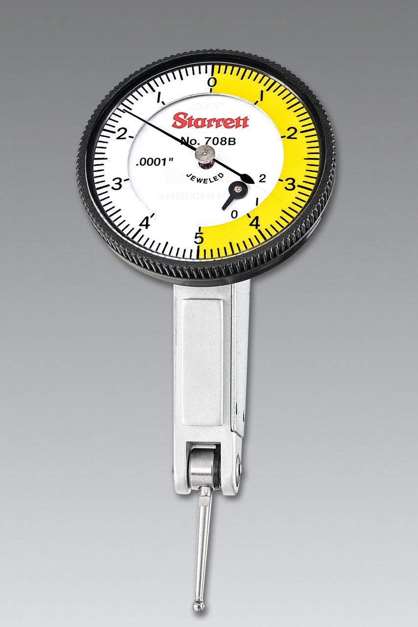
These test indicators offer an easy to read angled head and the flexibility of three dovetail mounts.
Digital electronic indicators minimize the chance of loss of data.
The back plunger type indicator provides the same ease of use in similar applications as the dial type drop indicator. Opposite to the spindle actuating the measurement, there is a plunger centered to the back of the indicator. This plunger, when activated by touching the workpiece, works in association with the dial and needle to visualize the measurement. The back plunger is usually used in smaller spaces for better readability vs. the drop type.
Next to arrive on the market was the test indicator, also known as a lever arm test or finger indicator by their design. The range of a test indicator is smaller than that of drop or back plunger types, and is primarily used for inspection, layout work or checking machined parts. The lever/ finger style contact moves in an arc instead of a linear line, so one needs to be aware of any cosine error when setting it up, as it is all about the position of the lever.
A dial test indicator is mounted at the end of a horizontal arm on an upright base post, where the post is adjustable on a slotted base. Another test indicator example is the universal dial test indicator. Various attachments, including a tool post holder, adapt it to a wide range of applications, such as checking runout of a spindle turned on a lathe.
Dovetail mount indicators provide another option for easy and accurate readability. The versatility of the angled head, combined with the three dovetail mounts eliminates the need for having both vertical and horizontal style test indicators.
Indicator Selection and Setup Tips
- Choose the accuracy and readout needed – don’t select .0001” (0.001mm) readout if .001” will do the job.
- Electronic/ Digital styles are best when the measurement data need to be collected, printed out or stored for future use.
- All dial indicators used worldwide fall into the following size ranges that relate to bezel diameters: Size 0 is a smaller dial indicator, having its own dimensions. Sizes 1 through 4 are AGD sizes. These sizes and the AGD dimensions are essentially the same for all manufacturers, except as noted.
- Accuracy: All indicators should be “loaded” 1/8-1/4 of a turn before testing or measuring. Most accuracies are specified plus or minus one graduation over the full range. This basically means a 2 ½ turn range. Longer ranges have slightly wider tolerances. AGD specifies 2 1/3 turn indicators to cover any particular range. The reason for this is an effort to get the most out of the indicator – the operator “loads” it to about 1 1/3 turns and sets zero on the master. The indicator will now show the accurate deviation for a full revolution, plus or minus.
The Dawn of Digital
All of these types of indicators began as mechanical with an analog (dial) readout similar to a wristwatch. Manufactured with gears, pinions, rubies, and racks, all parts need to function simultaneously for an accurate measurement. However, even the most qualified mechanical parts will wear in time, which can cause an inaccurate measurement. As technology advanced, the digital (electronic) indicator made its debut. To avoid mechanical parts wearing over time, these were and still are, engineered with a linear encoder to avoid future breakdown.
Digital indicators have grown in popularity and so have been replacing mechanical types in many instances. While both mechanical and digital indicators have the same accuracy dependent on the dial graduation and range of the tool, due to the gear to gear ratio on mechanical types, the tolerance can grow over a longer range. However, digital indicators (with glass scales) can hold their accuracy over an entire longer range. Digital indicators also offer key benefits including digital readout, total indicator reading (TIR), measurement storing, tolerance values, backlight for better visibility, presets, and importantly, data transmission for documentation and statistical process control (SPC).
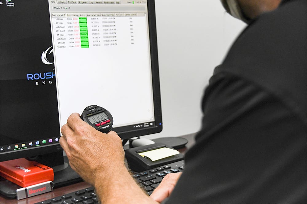
For accuracy, traceability and further analysis, wireless indicators can seamlessly transmit data, eliminating error-prone manual measurement data transcription.
Wireless Indicators
Since data transmission is crucial for collecting historical data and providing traceability, seamless connection to a wireless data collection system is a key capability. Originally designed with a cable plug in from the digital indicator to a PC, data collection has progressed to backpacks that plug directly into the tool. Now with wireless indicators on the market, a simple push of a button to send data to a PC, mobile phone or tablet is now possible.
One drawback with a digital readout is that some users like to determine the measurement variation by viewing the needle sweeping across a dial face indicator. However, there is significant benefit with digital indicators, particularly because they enable data transmission. All types are available in digital readout, drop, back plunger and test indicator configurations.
Latest Indicator Technology
State-of-the-art, highly accurate digital indicators that meet today’s demanding applications are available with selectable resolution choices from .0005/.0001/.00005” and are IP67 rated. Digital indicators allow for data collection with an end node plug in, while the wireless versions can send data with the simple push of a button to a PC, mobile phone, or tablet.
Since the late 1880s, indicators still play an important role in manufacturing. As they have advanced over the years, the initial concept of the indicator still holds true: a need to measure small measurements and angles. Who knows how indicators will continue to evolve—what advancement, what technology, will enhance the world of indicators?
How Digital Indicators Work
Digital indicators rely on three major components including an LED, a glass scale, and a reticle. The components all need to be precisely aligned with each other to give accurate measurements. First, the LED, has one function to shine an infrared light through the glass scale. Secondly, the heart of the indicator is the glass scale which is plated with a chrome pattern allowing light to pass through some areas while blocking light in other areas. This combination of light and dark areas will change as the glass is moved. The light pattern is detected by the third component, the reticle, using a series of infrared light sensors. Since this light pattern in any position on the tool is unique, the processor is able to convert it to an absolute measurement which is then displayed on the LCD. This is why users can turn the indicator off, move the glass scale along its travel while it is off and still have an accurate measurement as soon as the tool is turned back on.
Images (all courtesy of The L.S. Starrett Company)
Tim Cucchi, product manager-precision hand tools, The L.S. Starrett Co. For more information, visit www.starrett.com.
April 2022 | Volume 61 | Number 4