Geometric Dimensioning and Tolerancing
Measurement
Let’s review some of the elements of Geometric Dimensioning and Tolerancing. By Gregory S. Gay
I teach a metrology lab for Western Michigan University junior and senior engineering students and have been using GD&T for over 30 years in manufacturing. For most students, measurement and GD&T is a new subject for them. I get the opportunity to review the basic concepts each year. The following is a review of some of the terms and concepts.
General Rules
There are five general rules.
Rule 1: When only a tolerance of size is specified that tolerance controls both size and form.
Size controls form. Conventional plus and minus tolerance sets the limits of size and the feature form can be anywhere within this tolerance and would include extreme form variation. If the design and function of the part will allow a maximum variation of form then there is no need to add additional GD&T form or orientation controls.
Rule 2: When position or datums of size are specified, modifiers must also be specified.
This is an old rule and is now obsolete. Now when position or datum of size are specified regardless of feature size is assumed. MMC and LMC must be specified to be active and used. Look to the title block on the print to verify the Y14.5M standard being used.
Rule 3: When form/orientation is specified, the modifier regardless of feature size is implied.
This is still current. Regardless of feature size is assumed.
Rule 4: Screw threads, splines, and gears, tolerance and datum reference originate from the pitch cylinder axis.
Think center of the pitch circle. The pitch circles of a part used together forms a pitch cylinder the center being the axis. It is this axis that the tolerance and datum reference originate. For the longest time I did not fully understand. I would use minor or major diameter to measure or set up parts. Although both follow the pitch diameter to be correct the setup should locate off the pitch diameter. There are plugs and rings available that locate off the pitch diameter. If major or minor diameter is to be used it can be stated on the print under the feature control frame or datum symbol.
Rule 5: A virtual condition exists for features of size and datum features of size.
The way I think of virtual condition is how the mating part will see and interact with the part. The example I would use is a .500 diameter hole will accept a .500 diameter minus pin at any angle of the hole in part. However if the hole is angled to the surface a .500 minus pin will not pass through ninety degrees to the surface or datum. A smaller pin is required to maintain that ninety-degree relationship. The largest pin that maintains the ninety-degree relationship is the virtual condition. The axis of the virtual condition pin can now be used. The mating part “sees” this small pin as that is the size that will pass through the mating part at ninety degrees.
Size and Location: Anytime I measure a part, size and location are my prime interests. How big a feature is and where it is located. There are two types of tolerances, Tolerance of Size and Tolerance of Location. You have to stay within both tolerances. I measure all the size features first. It is faster to check and I need the results for calculation of GD&T bonus tolerance.
MMC and LMC: Maximum Material Condition is when the most material that can be present is in fact there. All the allowed material is there and the feature is in specification. This condition is known as Perfect Form. The smallest hole or largest pin is MMC. Least Material Condition is just the opposite, the largest hole and smallest pin allowed by size tolerance. LMC specified where wall thickness is important. MMC symbol is a circle with an M. LMC symbol is a circle with a L.
RFS: Regardless of Feature Size is assumed for all geometric tolerances. Back in the day a circle with an S was used. Today it is assumed the feature is RFS. Simply stated you have to stay within the size tolerance and the location tolerance regardless of how the feature of size changes there is no bonus tolerance. MMC and LMC must be specified to receive bonus tolerance.
Bonus Tolerancing at MMC: As the feature of size departs from MMC that amount is added to the Tolerance of Location. MMC must be specified in the location feature control frame using the circle with the M symbol to receive bonus tolerance. The example I use is a hole with a diameter of .500 +/-.010 and a location, true position diameter call out of Ø .010. MMC would be at .490, LMC at .510. If the hole size measured at .496. That would be .006 away from MMC and resulting in a .016 total tolerance of location with the bonus. If the hole was produced at the LMC limit of .510. The resulting tolerance would go up to .030. Bigger holes assemble easier and can be farther off location than ones produced at MMC.
Basic Dimensions: Theoretical exact. Has no tolerance of their own. Shown as a boxed dimension on the print. Basic dimensions do two things. They locate target datums and they locate tolerance zones. They locate a point in space and at that location a target datum or the center of a tolerance zone is located. The axis of a feature of size like a hole has to be in the zone.
Location Tolerance⌖: The location tolerance is found under the size tolerance associated with the basic dimension that locates the tolerance zone. The zone is normally circular or a cylinder in shape starting at one surface and extending through the part to the opposite surface. The axis of the feature must remain within this zone. The axis may be extreme angled, however must remain within the zone.
Actual Measured Tolerance Zone Dia = 2* √(A² + B²): For A and B use the X Difference and Y Difference. These values are the differences from the nominal, basic dimensions. The reason you times by two is to get the diameter from the radius. If the resulting number is smaller than the location tolerance then you are in tolerance and if larger you are out of tolerance. The number represents the size of the tolerance that the axis of the measured feature lies. In the example below that value would be .009 (.0089). This is smaller than the location tolerance of .010 so the part is in tolerance.
Training Aid: Sometimes it is helpful to see a visual of the concepts of GD&T positional tolerancing. This training aid was developed with the help of WMU Engineering Design Technology Major Leah Fernandez.
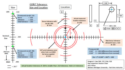
GD&T Tolerance: Size and Location
There is a lot of information displayed on this chart. However all the elements are included. Each week as part of the metrology lab, the students do the following:
It takes about four times to get 80 percent of the class to really understand the concept. Some of the common failure modes include:
A) Not understanding X Difference by using the 2.502 actual instead of just the difference of .002.
B) Using .010 positional tolerance as plus and minus on graft paper, instead of a diameter of .010.
C) Not knowing that MMC of a hole is the smallest size.
D) Charting actual size incorrectly
It helps to go through this process and I would encourage you to do a few trials.
This has just been a review of some of the elements of Geometric Dimensioning and Tolerancing. We have just scratched the surface of this subject.
The history of GD&T can be traced back to symbols being used in MIL-STD-8A,-8B,-8C. ANSI Y14.5 was published in 1966 and 1973. A new revision was published in 1982 and reaffirmed 1988. ASME Y14.5M-1994 was printed in 1994 and was reaffirmed 1999. ASME produced the standard again in 2009 and 2018.
It should state on the engineering drawing what the drawing standard that is being used. It is normally in small print within the title block.
To learn more I would highly recommend a purchase of the Y14.5 American National Standard as a hard copy and also one of the many available textbooks based on the standard. The standard by itself can be a tough read. The second book can be very helpful in breaking down the subject into manageable segments.
I wish you well on your GD&T journey.
A) Select a part with a hole from the part board
B) Measure the hole location
C) Create a simple GD&T print
D) Chart the hole location and size on 10 to 1 or 5 to 1 graph paper
E) Compute the GD&T location tolerance and the GD&T Tolerance with Bonus Tolerance
F) State if the hole is in tolerance or out of tolerance
Opening Image Source: teekid/Creatas Video via Getty Images.
Gregory S. Gay is skilled in the use of precision measuring tools and layout inspection. He has worked with the application of inspection and Geometric Dimensioning and Tolerancing (GD&T) principles for more than 30 years. Gay is an ASQ Fellow and is an ASQ Certified Quality Engineer (CQE), Quality Auditor (CQA), Quality Technician (CQT), and Quality Inspector (CQI). He has also been recognized as a Journeyman Mechanic in the Trade of Layout Inspection. Gay has instructed quality‐related classes for five community colleges, various companies and ASQ. Gay is currently a part time instructor at Western Michigan University where he instructs a Metrology Lab course.
April 2022 | Volume 61 | Number 4